 Dávid Máté
So I came upon this design on Thingiverse, and I always wanted such a lamp.
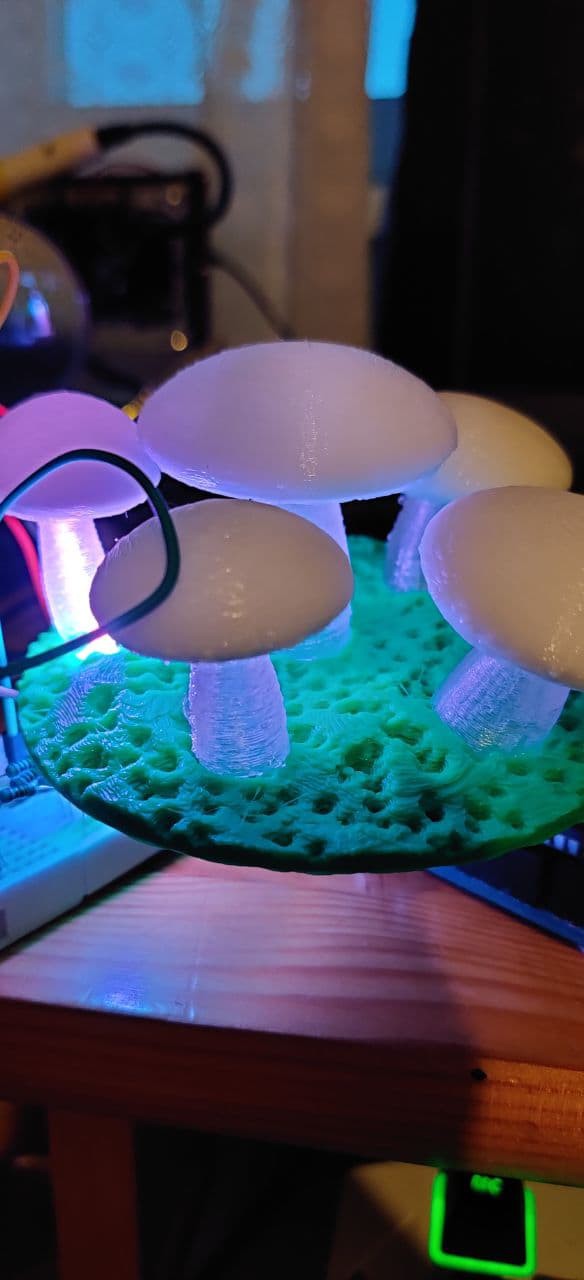
The project started by sending the stl files to my 3D printer (I'm using an Anet A6 btw). The base was printed by using a black PLA filament, the "ground" part with green, the stems of the mushrooms are with translucent white and the shroom caps with opaque white. The parts are held together with superglue. (I haven't fixed the base to the top yet)
The original design was using smart RGB LEDs with a PIC as the microcontroller. I prefer attiny, so I tried to implement the functionality using an attiny85. I also don't have any spare smart LED's around, so that's also out of the question. In the past years I've used elcojacob's ShiftPWM library with an Arduino Duemilanove with great success, however that library doesn't work on an attiny. You can find bigjosh's ShiftPWM Redux on some forums, this is a modified version of the aforementioned one, which can compile on an attiny85. As it's usual I've started experimenting with the electronics on a breadboard.
Turns out that bigjosh's library also has its flaws. The timing is really off, so if you choose base colors, you are good, but if any color component isn't full brightness, it'll start blinking like it's christmas. I've started to tinker with the library a bit, replaced Timer0 with Timer1, set up a different clock prescaler, and voilá, I have a working shift pwm on an attiny. It's pretty much a WIP, but you can find it on my github.
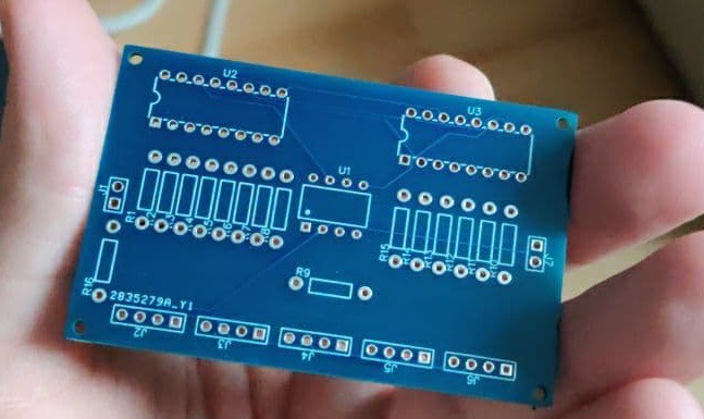
When everything seemed fine, I designed a PCB, and I've ordered it from JLCPCB. This was my first time ordering a PCB and not etching myself, but I had to try this as well. They also look pretty nice!
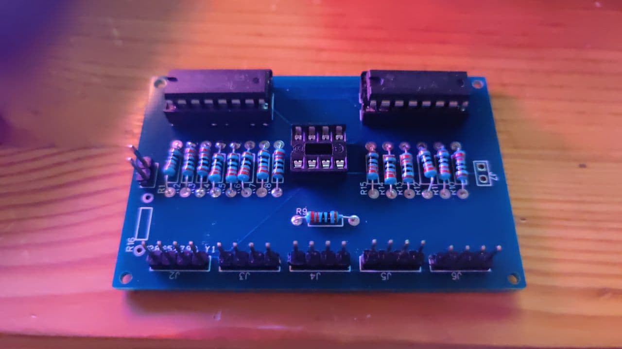
Currently the lamp goes through a slow HSV rainbow effect, but I'm planning to make some other ones. The PCB also has a spot for soldering a photoresistor on, but I'm not using it yet. There'll also be a second revision of the PCB, as I forgot to add the annotations on the silk screen. So if you try to make this using my first version PCB, all resistors are 220 Ohms, except for R16, which is a 10k one, it's used for the photoresistor on J7. You give power on J1, the rectangular is +5V, the circular is GND. The LEDs have the common pin over the prefix. (So if you view the picture above, from the left to right it's red, common, green, blue)
This is the second prototype, which will have detachable LEDs and power source
Discussions
Become a Hackaday.io Member
Create an account to leave a comment. Already have an account? Log In.