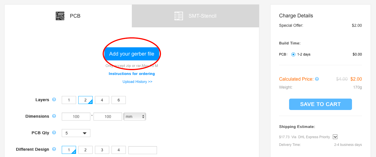
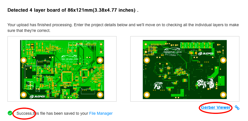
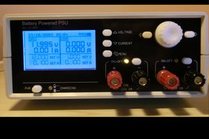
The battery tester is a board that will be used to test the charging/discharging of the battery. We charge/discharge the battery via the MOSFETs in the IGBT module, and we are able to control the charge/discharge process by sending signals to these MOSFETs. We can monitor the voltage of the battery multiple ways.
The key components in this board are the IGBT Module and the MCU.
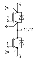
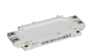
- IGBT (FF600R12ME4): The IGBT module is a transistor which has the high input impedance and switching speeds of a MOSFET with the low saturation voltage of a BJT. This component takes in signals from the MCU and drivers to control the charge/discharge of batteries.
![]()
- Features:
- Low VCEsat (Saturation voltage, collector-emitter)
- Tvj op (operating junction temperature) = 150°C
- VCEsat with positive temperature coefficient
- High power density
- Isolated base plate
- Standard housing
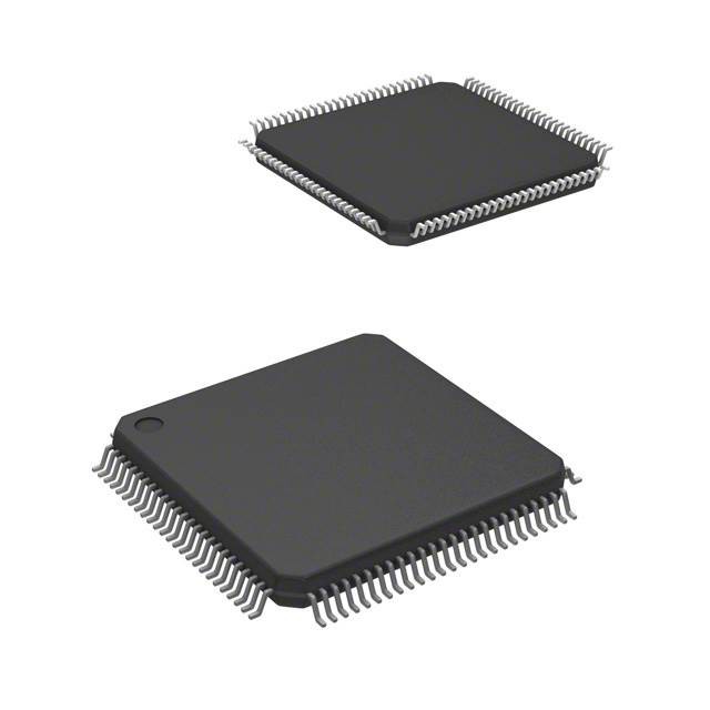
- MCU (STM32F777VIT6): The MCU is the brain of the board. It takes in signals, performs calculations, then outputs signals. It sends out \Enable, an active low signal, to the IGBT to turn it off if needed.
![]()
- Features:
- Arm® 32-bit Cortex®-M7 CPU with DPFPU, ART Accelerator™ and L1-cache
- Dual mode Quad-SPI
- Clock, reset and supply management
- Up to 168 I/O ports with interrupt capability
- Low-power
- Debug mode
 Manuel Tosone
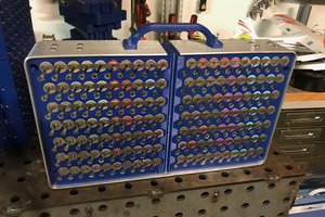
 Ampeater
 AirCruiser
 Hulk
Hulk