Close
0%
0%

PP04 - Camel computer

Edit, assemble, program and debug your PIC18 application... on another PIC. Complete IDE on single chip. Undocumented PIC features exploited

Similar projects worth following
This is device I built for DesignSpark chipKIT Challenge 2012, but the project has no stable position on web, so I decided to conserve it here.

In short, it is simple handheld computer, running on PIC32, built from scratch and not based on any OS. It features command-line interface, operating above internal SD card FAT32 storage, with commands entered through simple keypad with tradition cell-phone like layout.
It has a few user programs, like text editor, PIC18 assembler, PIC18 FLASH programmer and PIC18 debugger. Especially the debugger part was really hard thing to do, as it involved partially guessing/reverse engineering debug protocol and registers of PIC18 which are not documented. Except of it, there is also BrainFuck interpreter and BASIC interpreter, so this device could be used not just as PIC18 IDE.

This project is quite old, I worked on it for a few years and there are currently no plans for reviving, as I lack time for it.

A long time ago, at age 11 or 12, when I was tinkering with electronics, I saw some early notebook computer and I was really impressed. Since that moment I wished to build my own computer, independent from mains supply, compact and small enough to bring anywhere I want.

That time I didn't have enough knowledge and experience to accomplish such as goal, but this idea didn't leave me until now. However situation is slightly different now. Portable computers are not expensive and rare those days and you can buy small Android powered computers under 100USD, completely capable doing what I dreamt of. After all, my old dream doesn't leave me, because there is another important factor - DIY aspect. Having handmade device (from both hardware and software perspective) gives user, except of ultimate nerd status symbol, satisfaction from creative process during soldering and programming, absolute control over device behavior resulting in no viruses or similar diseases of today’s computers.

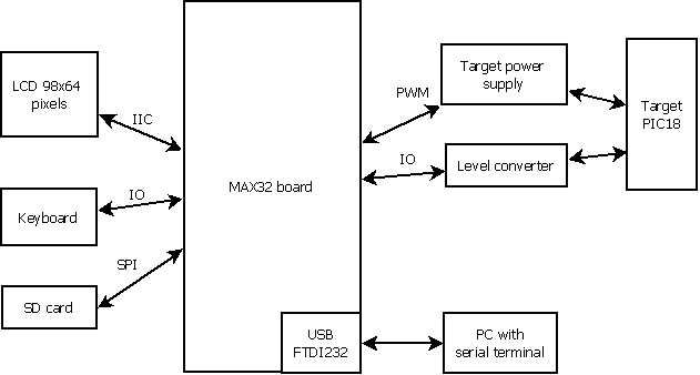
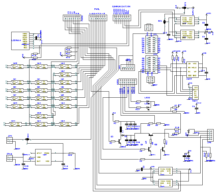
PP4 is Pic Pic programmer, the fourth. Pic Pic because you are programming one PIC (PIC18) with another PIC (PIC32), 4 means fourth incarnation of this idea. I started with PIC18, moved to dsPIC33 because of higher power, but returned to PIC24 because of lower current consumption, but taking all advantages of PIC32 in last one. As development proceeded, features were added, bringing most progress in fourth version - thanks to PIC32 (easy development and porting some pieces of code, high power and feature rich silicon products) and MAX32 development board (stable development platform, wide variety of Arduino compatible extensions and availability) it was possible to bring SD card support and grow simple CLI operating system for PIC32 around my original goal.

A friend of mine calls this device “Camel computer” meaning you can program your favorite PIC while riding a camel through endless deserts…

I think the most interesting point of this project is reverse engineering/guessing of internal debug engine of PIC18, resulting in physical debugger realisation.

debug_executive_sources.zip

sources for debug executives in target PIC18 - three variants for PIC18Fxxxx, PIC18FxxJxx and PIC18FxxKxx

x-zip-compressed - 3.53 kB - 07/29/2016 at 23:18

Download

CK74283_photo.zip

Files for DesignSpark chipKIT Challenge 2012

x-zip - 22.62 MB - 07/29/2016 at 06:16

Download

CK74283_sources_MPLAB.zip

Files for DesignSpark chipKIT Challenge 2012

x-zip - 2.00 MB - 07/29/2016 at 06:14

Download

CK74283_designspark_pcb_files.zip

Files for DesignSpark chipKIT Challenge 2012

x-zip - 195.74 kB - 07/29/2016 at 06:14

Download

CK74283_abstract.zip

Files for DesignSpark chipKIT Challenge 2012

x-zip - 172.26 kB - 07/29/2016 at 06:14

Download

View all 6 files

  • Power source

    jaromir.sukuba07/04/2014 at 11:16 0 comments

    This device was designed with low power consumption in mind. That’s why I choose operation speed of PIC32 to 4MHz, with peripheral bus clock 2MHz. Running 80MHz PIC32 at 4MHz may seem strange, but this power is quite enough for such as application. Old computers (I mean those with 6502 or Z80 CPU, not your old dual-core system) ran at about the same clock frequency, but it were simple 8-bit architectures, so my system has higher power after all. On the other hand, thanks to using low-power LCD the complete current consumption of MAX32 board with my add-on falls down to 12mA (after unsoldering indication LED from MAX32 board, taking 4mA of current), so this enabled me to run this device for at least ten hours from small 140mAh Li-Ion cell. This also allows using solar cells (practically tested with this one) or small wind generators (untested, but interesting option – for example here) or even water generators (like this one). All those option allows direct powering of this device, but irregularity in power supply can cause open file to be lost. This is reason for powering PP4 from Li-Ion cell and using power from those energy sources for charging this Li-Ion cell, even when PP4 is not turned on.

    That is why I created extension for powering PP4 from small Li-Ion battery or solar cell. I measured parameters of this solar cell – the weak February sunlight can make it deliver circa 5,5V at open circuit and 80mA into short circuit, so 0,5W is quite reasonable estimation of its power capabilities. I built a simple circuit:

    When there is no voltage on input, PFET (Si2333) transistor opens and supplies output from battery. 22K resistor between its G terminal and ground ensures that transistor is fully open.

    Input (from solar cell, USB cable or standard 5V wall wart) is brought to output through diode BAT48 and G terminal of PFET, closing D-S channel and removing load from battery. MCP73831 works as Li-Ion charger, charging cell between pins 2 and 3. 20K resistor on pin 5 sets the charging current, on this case it is around 50mA. LED on pin 1 indicates the end of charging process.

    There are more sophisticated ways of achieving functionality with both battery and solar power, but this one is simple and usable enough for me.

  • Software

    jaromir.sukuba07/04/2014 at 10:22 0 comments

    Software

    Most of work was done on software side. It can be divided into two parts – system kernel and user programs. Kernel operates above FAT32 file system and currently supports only single logical (and) physical drive. All user programs are currently in FLASH memory, build together with kernel, however during writing of this document, I’m writing and testing new version, allowing running binaries from SD card.

    System kernel

    This part of software allows running user program and provides standardized interface to it. There is a set of commands allowing operation with file system and selecting standard IO interface.

    After reset, invitation message is displayed, starts initialization of SD card and if it is successful, message prompt appears:

    Kernel now accepts commands, for example ls is such as “non-destructive” command, not altering anything, just listing files on current directory.

    Example above shows listing in case there are four files. Maximal displayable format is 8 characters for filename and two characters for extension, however, kernel can – internally – work with standard 8:3 filenames. LFN support is not enabled (though simple to implement) now, as using long filenames wouldn’t be practical for such as simple device – there are no technical reasons for not implementing it. I will not go through all commands supported by kernel (comprehensive summary can be found in appendix A).

    Messages are scrolled on display, one can see history of commands by using “up” and “down” keys to unscroll it back. Maximum history size is 128 lines.

    Though kernel allows program to 
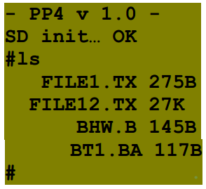
use standard IO interface, not all programs use it – there are two exceptions: ED and DE. Those operate directly above display and keyboard buffer, so its operation is limited to local display and keyboard. I’m working on new kernel supporting full-display operation, so those exceptions will disappear.
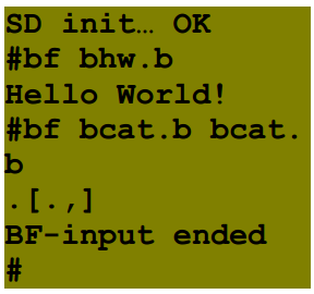
    User programs

    There is a few programs implemented into this release, including text editor, PIC18 assembler, PIC18 programmer, PIC18 debugger, then programs not related to PIC18 programming – BF interpreter, BASIC interpreter.

    BF - BF interpreter

    BF is one of esoteric programming languages, probably the most famous one, interesting by its minimalism, however surprisingly functional. It was developed for amusement while experimenting how small compiler can be written for this language. It was released in 1992 as compiler for Amiga computer (68000 based), however variants of it were written for many other platforms, PIC32 with PP4 including. For more information about BF, you can visit form example Wikipedia page.

    BF can be invoked from PP4 command line:

    bf <source file> <input file (optional) >

    This example:

    shows running BF interpreter with one parameter (only source file) and with two parameters (both source and input files). First example runs famous “Hello world” example, second runs “cat” program (copying input to output), while parameter is source file itself, so this effectively prints content of source file to display, being equivalent to ad kernel command.

    Cell size is 8 bits, array size is 30000 cells, stack depth 5000 levels, input is redirected from file only as input from stdio would not be practical. When end of source is encountered, BF interpreter returns to system kernel, when end of input file is encountered, BF interpreter returns with “BF-input ended” message (see example above).

    BA - BASIC interpreter

    This interpreter is based on uBasic by Adam Dunkels. It provides all usual BASIC commands while maintaining simplicity and portability of code.

    This interpreter can be invoked from command line:

    ba <source file>

    This example:

    runs simple demo program

    10 gosub 100

    20 for i = 1 to 3

    30 print i

    40 next i

    50 print "end"

    60 end

    100 print "subroutine"

    110 return

    Maximum size of interpretable file is 40000 bytes.

    PIC 18 development set

    This is trio of programs, allowing cross-development for PIC18 on PIC32...

    Read more »

  • Hardware

    jaromir.sukuba07/04/2014 at 09:56 0 comments

    Hardware

    All hardware is built around MAX32 development platform, as extension to be stacked on original board, creating compact device.

    Extension contains everything needed to turn MAX32 into PIC18 programmer - mainly Vpp generator (voltage to bring on MCLR line to enter programming mode of some PIC18 devices), voltage level converters for data lines, data storage, power supply, keyboard (made from discrete switches) and display (tiny and low-power 98x64 pixels), with strong accent on low power operation. In fact, there is nothing much to add, due to completeness of MAX32 board and usage of PIC32 peripherals.

    PIC18 programming interface

    This part of circuit is built around Q2 to Q5 and level converters 74LVC1T45.

    Q2 is power switch for step-up converter, its base is feeded from PWM generator in PIC32. Depending on frequency and duty cycle, on capacitors C8 to C10 voltage rises above level on C7, C11 and C12. This voltage is brought into voltage divider R5 and R6, dividing high voltage to level suitable for AD converter in PIC32. This allows to implement PID regulator, keeping high voltage at needed level (13,5V for PIC18Fxxxx and 8,5V for PIC18FxxKxx).

    Q3 is high-side switch, switching high voltage on its emitter to MCLR target pin (T_MCLR). Q4 is part of switch, enabling Q3 to be switched from 3,3V CMOS PIC32 level. When Q3 is off, Q5 allows T_MCLR to be pulled down.

    PGC and PGD lines of target PIC (T_PGC and T_PGD) are controlled by two 74LVC1T45 drivers, what allows target to be powered by 1,8-5,5V source. R13 and R14 are pull-down resistors ensuring logic levels for correct operation.

    Data storage

    Data storage is possible in two ways - SPI FLASH memory and Micro SD card.

    SPI FLASH memory is currently unpopulated, but there are more options at this position. You can populate SPI FLASH (25VF161 or similar), SPI EEPROM (25LC256 or similar) or SPI RAM (23K256) due to universal footprint.

    Micro SD card (uSD) is connected in simpler SPI mode (as opposed to full-blown 4-wire interface), using SPI peripheral of PIC32.

    Power supply

    There is option on board to supply target and circuits of upper half of PP4 from separate voltage regulators. EN pins of regulators are brought to PIC32 pins, however this feature is not used now. All circuits are supplied by MAX32 board voltage regulator.

    There is also space for MCP73831 charger, this one is unpopulated too.

    User interface

    This part of circuit consists of two main parts - display and keyboard.

    Display is small 98x64 pixel LCD, with low power operation (circa 200uA), with IIC interface. This interface uses IIC peripheral in PIC32, allowing easy implementation of this part of user interface. Display is used in text mode (there is no font generator in this device, so it is emulated in PIC), with 8 lines by 16 characters.

    Keyboard consists of 20 discrete buttons, because such as complete keyboard is almost unobtainable. Those buttons are not very pleasant to work with, but it is simple, cheap and available solution. Keyboard is arranged into three parts - cursors keys (up, down, left, right) arranged into group of four buttons, alphanumeric area (12 keys to write numbers or letters, the same principle as keyboard of mobile phone) and special keys (enter, escape, shift and backspace).

    Except of local keyboard and display, there is option to communicate through serial communication channel, as an alternative terminal. There is kernel command to switch between terminals. Standard communication parameters are 9600 baud, no parity, no handshaking.

View all 3 project logs

Enjoy this project?

Share

Discussions

Similar Projects

Does this project spark your interest?

Become a member to follow this project and never miss any updates