 jaromir.sukuba
Software
Most of work was done on software side. It can be divided into two parts – system kernel and user programs. Kernel operates above FAT32 file system and currently supports only single logical (and) physical drive. All user programs are currently in FLASH memory, build together with kernel, however during writing of this document, I’m writing and testing new version, allowing running binaries from SD card.
System kernel
This part of software allows running user program and provides standardized interface to it. There is a set of commands allowing operation with file system and selecting standard IO interface.
After reset, invitation message is displayed, starts initialization of SD card and if it is successful, message prompt appears:
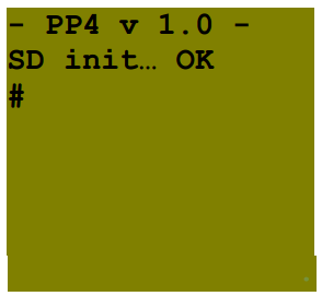
Kernel now accepts commands, for example ls is such as “non-destructive” command, not altering anything, just listing files on current directory.
Example above shows listing in case there are four files. Maximal displayable format is 8 characters for filename and two characters for extension, however, kernel can – internally – work with standard 8:3 filenames. LFN support is not enabled (though simple to implement) now, as using long filenames wouldn’t be practical for such as simple device – there are no technical reasons for not implementing it. I will not go through all commands supported by kernel (comprehensive summary can be found in appendix A).
Messages are scrolled on display, one can see history of commands by using “up” and “down” keys to unscroll it back. Maximum history size is 128 lines.
Though kern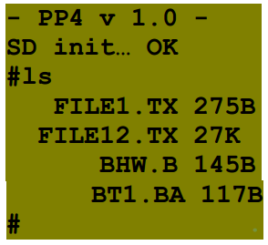 el allows program to
use standard IO interface, not all programs use it – there are two exceptions:
ED and DE. Those operate directly above display and keyboard buffer, so its
operation is limited to local display and keyboard. I’m working on new kernel
supporting full-display operation, so those exceptions will disappear.
el allows program to
use standard IO interface, not all programs use it – there are two exceptions:
ED and DE. Those operate directly above display and keyboard buffer, so its
operation is limited to local display and keyboard. I’m working on new kernel
supporting full-display operation, so those exceptions will disappear.
User programs
There is a few programs implemented into this release, including text editor, PIC18 assembler, PIC18 programmer, PIC18 debugger, then programs not related to PIC18 programming – BF interpreter, BASIC interpreter.
BF - BF interpreter
BF is one of esoteric programming languages, probably the most famous one, interesting by its minimalism, however surprisingly functional. It was developed for amusement while experimenting how small compiler can be written for this language. It was released in 1992 as compiler for Amiga computer (68000 based), however variants of it were written for many other platforms, PIC32 with PP4 including. For more information about BF, you can visit form example Wikipedia page.
BF can be invoked from PP4 command line:
bf <source file> <input file (optional) >
This example:
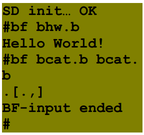
shows running BF interpreter with one parameter (only source file) and with two parameters (both source and input files). First example runs famous “Hello world” example, second runs “cat” program (copying input to output), while parameter is source file itself, so this effectively prints content of source file to display, being equivalent to ad kernel command.
Cell size is 8 bits, array size is 30000 cells, stack depth 5000 levels, input is redirected from file only as input from stdio would not be practical. When end of source is encountered, BF interpreter returns to system kernel, when end of input file is encountered, BF interpreter returns with “BF-input ended” message (see example above).
BA - BASIC interpreter
This interpreter is based on uBasic by Adam Dunkels. It provides all usual BASIC commands while maintaining simplicity and portability of code.
This interpreter can be invoked from command line:
ba <source file>
This example:
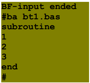
runs simple demo program
10 gosub 100
20 for i = 1 to 3
30 print i
40 next i
50 print "end"
60 end
100 print "subroutine"
110 return
Maximum size of interpretable file is 40000 bytes.
PIC 18 development set
This is trio of programs, allowing cross-development for PIC18 on PIC32 PP4. It consists of editor, simple two-pass assembler, programmer and debugger.
ED
ED is simple WYSIWIG editor, designed for work with PIC18 assembler sources.
It can be invoked by calling
ed <input file>
If input file is not submitted, then ed creates empty space in memory, which can be edited and saved. If input file exists, its content is loaded and edited in memory. No changes to actual file is done while not saved from user command.
Its layout looks like this:
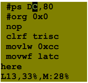
Where first seven lines of display show actual content (with cursor on first row) and last status line telling cursor is on line 13, what is 33% of overall number of lines in file and this file occupies 28% of allocated memory.
There are a few limitations for this editor: line length can be max. 16 characters, excluding <NEW LINE> character, currently there is only 2000 bytes allocated for editor in memory, so there is no way of editing longer files. Former issue is fixed in 1.1 version, space is expanded to 40kB.
Currently, ED cannot operate through standard IO mode – it operates only above local display, however it can be run from command line, debug results can be observed only on local display.
AS
AS is simple assembler for PIC18 MCU, enabling creating cb file (see appendix B for description of cb format). This file contain binary images of program memory, configuration bytes, PIC configuration (used by debugger and programmer) and debug info (used by debugger only).
It is invoked in form
as <input file> <output file>
It messages any error that could happen during assembly, in ideal case it looks like this:
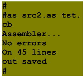
This output informs that assembler was invoked, assembly of input file with 45 lines was successful and output file was saved.
There is list of possible error codes:
1, Unknown opcode on line x – self explanatory
2, Bad px on line y – first (x=1), second (x=2) or third (x=3) parameter of instruction on line y is invalid
3, 8 bit over range on line x – parameter that is expected to be in range 0..255 is out of range on line y
4, 11bit over range on line x – the same as before, for parameter 0..2048
5, Deftable over on line x – too much definitions in this file, first definition over range is on line x
6, Unknown definition on line x – definition on line x is not found
PG
PG is programmer for PIC18 devices, reading input from cb file accessing PIC18Fxxxx, PIC18FxxFxx and PIC18FxxJxx devices. Though PIC18F25K20 was most intensively tested, all other devices from mentioned families should work. Tested were also 18F4221, 18F45J10, 18F4620, 18F26K22.
Assembler is invoked in form
pg <input file>
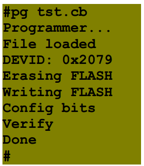
And in ideal case its output looks like this:
 (notice that number of “display”
lines was increased in order to fit all data, which would be scrolled up on
real device)
(notice that number of “display”
lines was increased in order to fit all data, which would be scrolled up on
real device)
This output shows that cb file was successfully loaded, device with ID 0x2079 was found, everything was programmed correctly and FLASH was verified and OK. If verification would find any error, particular byte at which first error was found is outputted.
DE
DE is in-circuit, source level debugger for PIC18 devices. Supported devices are the same as for PG application. It accepts cb files as binary files and ASCII text files as source files.
It is invoked as:
de <cb file> <source file>
After this, debugger tries to load file, erase and program FLASH, and start communication with debug executive and read signature from debug executive. In ideal case it looks like this:
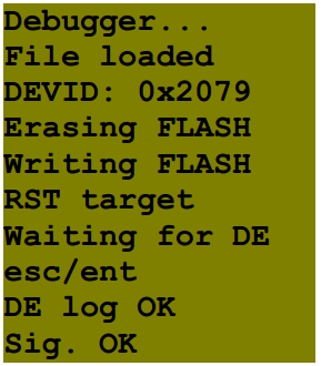
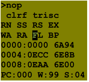
notice that number of “display” lines was increased in order to fit all data, which would be scrolled up on real device). If there is a problem with communication to debug executive, it will stop after line “Waiting for DE”, with option esc to cancel process and enter to repeat it. If this process runs as expected, screen is cleared and debugger windows takes place:
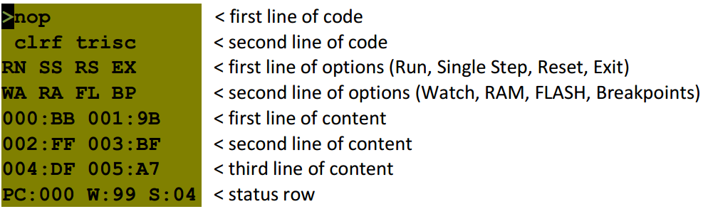 It shows cursor on first position
of first row. There are two lines of source code (on row 1 and 2), two lines of
options (rows 2 and 3), three lines of selected content (row 4, 5 and 6) and
finally status row, showing values of PC, WREG and STATUS.
It shows cursor on first position
of first row. There are two lines of source code (on row 1 and 2), two lines of
options (rows 2 and 3), three lines of selected content (row 4, 5 and 6) and
finally status row, showing values of PC, WREG and STATUS.
User can select functions by moving cursor using cursor keys:
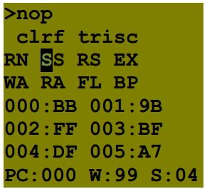 Here is cursor moved to SS option
(Single Step). After pressing enter, this option is executed:
Here is cursor moved to SS option
(Single Step). After pressing enter, this option is executed:
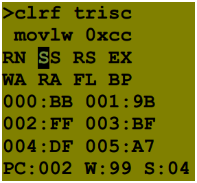
Notice change of PC and showing second line of code as actual instruction. After pressing enter again (SS option is still selected) another single step is executed:
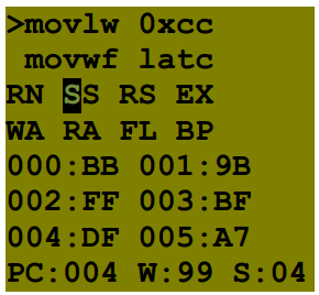
PC is double incremented again and “clrf trisc” instruction is executed. LEDs on PORTC would light up, if there is valid value on LATC. Another pressing of enter would do another single step:
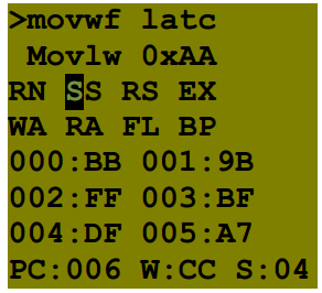
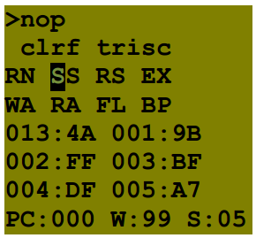
Notice that PC is increased again and WREG value is changed by last instruction (“movlw 0xcc”). After selecting RS option, reset of target is executed:
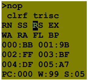
Selecting EX option would result in leaving DE application and return to system kernel. RN option will start running of code in target PIC
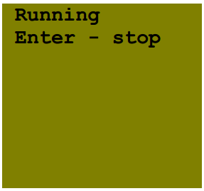
As application suggests, enter
will stop target and allows debugging of target. Second option line allows
selecting what will be displayed on content lines while debugging. One can
select WA (watch), RA (RAM), FL (FLASH) and BP (breakpoint) options. Default
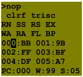
view is WA, user can change it to RA in the same way as for options before: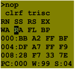
There are viewable addresses from 0x000 to 0x1B, in twelve bytes. One can also selectFLASH view:
There is viewable range 0x0000 – 0x0009, in six words. After selecting BP view, user can view placement of breakpoints:
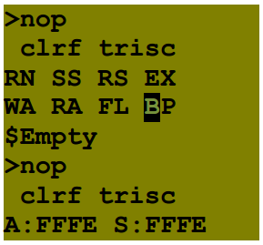
There is information about actual breakpoint (at address 0xFFFE, currently unavailable) and breakpoint to be set. Dollar sign shows current line in source code where breakpoint resides.
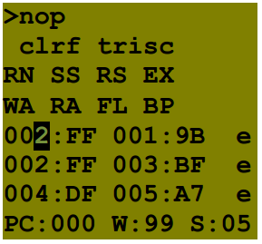
One can also change range of content lines that are currently showed. We will demonstrate it at watch view; user selects watch view and moves cursor to content line:
After pressing shift button, cursor is “locked” to current address and pressing buttons up or down changes address, while symbol “e” is visible on end of lines, indicating edit mode.
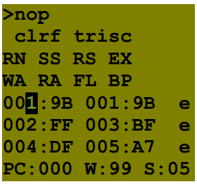
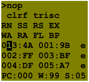
Another press of up key increments address again:
Moving left allows to change higher orders of address:
Pressing shift again “unlocks” edit mode and user can continue debugging.
This way user is able to view any RAM memory address. The same procedure applies to other options (RA, FL or BP).
Debugger is limited to one breakpoint, it is currently unable to export any output. It cannot operate through standard IO mode – it operates only above local display, however it can be run from command line, debug results can be observed only on local display (the same IO limitations as for ED).
Debugger DE is based on my research work, as debug specifications for PIC18 were never published, so I spent a lot of time putting puzzle together. A lot of information was guessed only, however debugging works as intended. For more details about debug mode of PIC18 devices, see my homepage.
Discussions
Become a Hackaday.io Member
Create an account to leave a comment. Already have an account? Log In.