Extremely simple electronic design, bare minimum.
From a top down view, +3.3v and Gnd are broken out from the Arduino onto a small piece of perf-board, and ALL switches, buttons, encoders and pots wire into a GPIO on the Arduino Due and a + or - connection as required. Then the Arduino Due is simply connected via USB to the computer. Everything else is essentially structural / aesthetic etc.
I use CAT5 twisted pairs stripped and soldered to each switch/pot/etc and soldered straight to the +3.3v or Gnd breakout board appropriately, or is terminated with a .1inch pin header for plugging into the Arduino Due.
Literally every switch is wired to a Gnd connection and a GPIO pin on the Arduino Due.
There is one exception in my case, where I'm using a three position switch, you obviously don't need to do this to make your own. The three position switch is connected to two GPIOs with this table -
| Switch Position | GPIO1 | GPIO2 |
| 0 | Off | Off |
| 1 | On | Off |
| 2 | Off | On |
All Potentiometers are wired to +3.3v and Gnd, and each wiper goes to its own Analog In on the Due.
There are two rotary encoders, wired up with a GPIO switch for pushing down on the encoder, and wired to +3.3v and Gnd, and also CLK and DAT lines for the encoder. I'm using some custom code for this that appears to work a lot better than the Arduino Libraries (i.e. responds better to rapid rotation).
The Yoke operates on a design I found on some YT videos exploring the inner workings of some more expensive commercial flight yokes on the market. There is a (relatively) cheap Saitek offering, but this has a lot of downsides.
I estimate without design, labour and time costs, this project cost no more than roughly £100 or less depending upon how much you're using from your hoarding stash. In my case if I exclude costs for all the stuff I bought before this project began, then we're talking only £20.
The 3D printed parts were all iteratively designed in Fusion360 and printed on my trusty PrintrBot Simple Metal Black (w/ extended X bed). As is clearly evidenced, the project evolved a lot over time, and went in this order -
- Envisaged a flight controller with Yoke, due to upcoming MS FS 2020. Before committing, I carried out some Proof of Concept Arduino tests to be sure it will all work together - this just consisted of using the MHeironymus Joystick library samples, and connect up a bunch of switches, some Pots on the Analog Ins, and tested it in Windows. Worked flawlessly although a LOT of question marks were raised regarding its integration with the Flight Simulator software - I knew it would connect and register switches but not necessarily work with toggle switches.
- Thought of making a separate switch box and yoke, and proceeded to design the switch box first with desk mount. The switch box also needed to connect directly to the Arduino Due so I also 3D printed a box for that, designed in such a way that I could mount the panel in front of it to conceal the circuitry.
- The yoke physical design is a slide in-and-out elevator with aileron rotation on the yoke. At this point still thinking about how to carry this out - settled on a rack+pinion for the elevator, and a simple 1:1 gearing for the aileron, all mounted to in-out oriented linear rail and carriage with LM8UU bearings. This carriage will accommodate places for the two potentiometers. The elevator pot is mounted 90deg from the carriage and is pinioned, this gear meshes with the rack on the left side of the linear rails. The aileron is dealt with by two skate bearings on a length of 8mm threaded rod thru the centre of the carriage, to allow rotation, then geared 1:1 to its potentiometer.
- Finally realised that all of it will need to be plugged into the Arduino Due permanently, so after I had 'prototyped' the yoke design on a sheet of Acrylic, I decided to mount the Control box to the Yoke, which had to sit high up to accommodate the movement of the yoke. I proceeded...
 Juan M. Casillas
 Lex Kravitz
 Maximiliano Palay
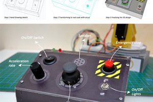
 Ahmed Azouz