 Subhajit
This smart relay has the following features:
This Smart Home System has the following features:1. Home appliances control from WiFi (Blynk App)
2. Home appliances controlled with manual switches.
3. Home appliances controlled by TV Remote (Infrared)
4. Relays controlled by temperature & Humidity sensor (DHT11) automatically.
5. Home appliances controlled by Dark Sensor (LDR).
6. Monitor LIVE temperature & humidity reading on the smartphone.
7. Monitor real-time status on the Blynk App
8. Inbuilt Arduino so Arduino code can be uploaded to the relay module.
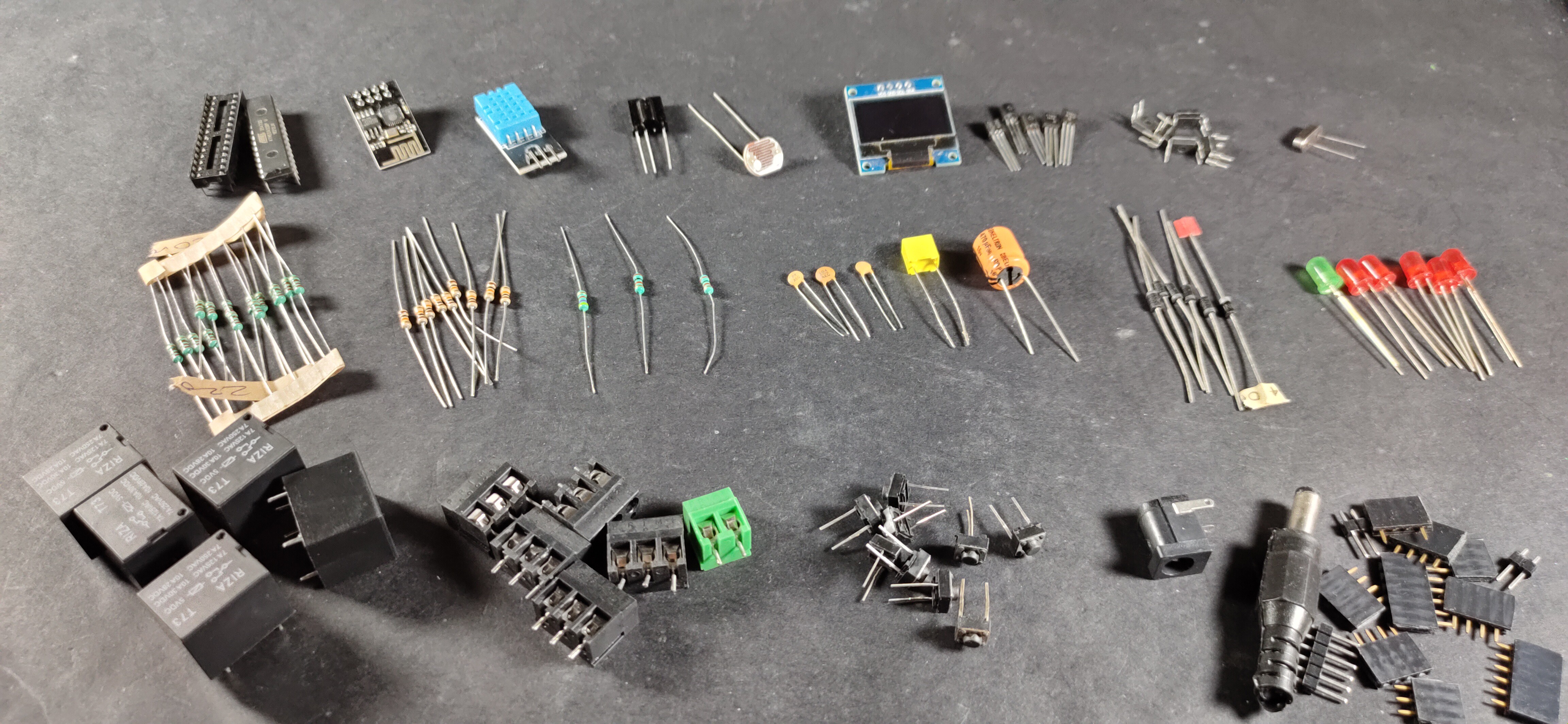
Component List:
1. ATMEGA328P microcontroller with bootloader
2. ESP01 WiFi Module
3. DHT11 Sensor
4. OLED Display
5. 1738 Infrared Receiver
6. PC817 Optocoupler (5 no)
7. BC547 NPN Transistors (5 no)
8. 1N4007 Diodes (5 no)
9. 1N4001 Diode (1 no)
10. LEDs 5mm (6 no)
11. 22pF Capacitors (2 no)
12. 100nF (104) Capacitor (1 no)
13. 470uF 25V DC Capacitor (1 no)
14. 220-ohm Resistors (15 no) (R1-R10)
15. 1k Resistors (1 no)
16. 10k Resistors (9 no)
17. 2k (1no) & 4.7k (1no) Resistors
18. LDR (1 no)
19. 16MHz Crystal
20. Push Buttons (9 no)
21. 5V relays (5 no)
22. Jumper (2no), connectors, IC base
23. AMS1117 3.3V voltage regulator (1no)
24. FTDI 232 USB to Serial interface board or Arduino UNO
Circuit Diagram:
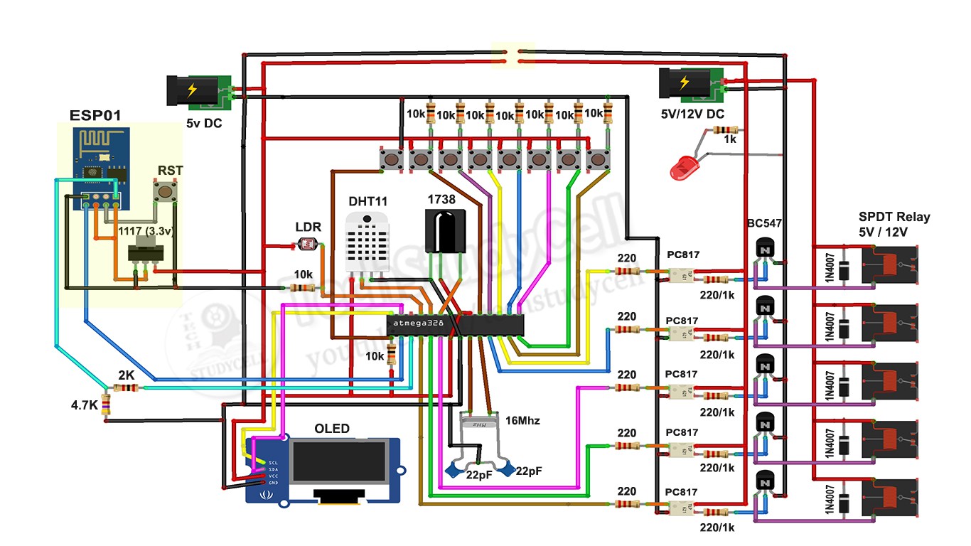

This is the complete circuit diagram for this home automation project. I have explained the circuit in the tutorial video.
I have used the ATMEGA328P micro controller to control the 5 channel relay module. I have also connected the ESP01 WiFi module, 1738 IR receiver to control the relays from Blynk App (Mobile) and Infrared remote. And DHT11 temperature & humidity sensor and LDR to control the relay automatically.
In this circuit, we can use both 5V or 12V relay but we have to change the resistors accordingly as mentioned in the circuit.
Please watch the complete tutorial video where I have explained all the steps.
SUBSCRIBE our YouTube channel for more such projects:
https://www.youtube.com/c/techstudycell?sub_confirmation=1
Different Mode of the Smart Relay Module
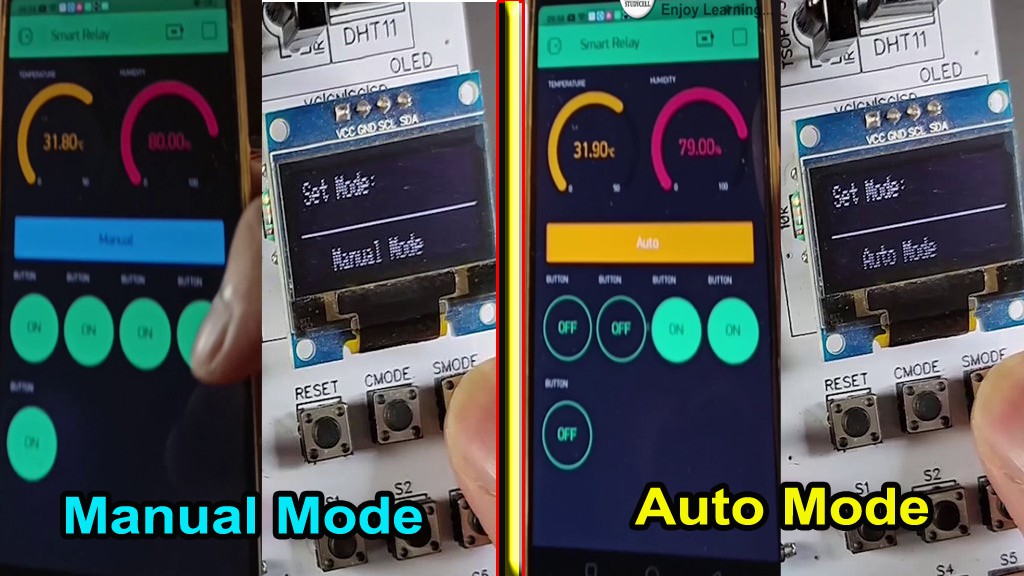
In this Smart home project we can control the relay module in two modes:
1. Manual Mode
2. Auto Mode
You just need to press the CMODE button to change the mode of the relay module.
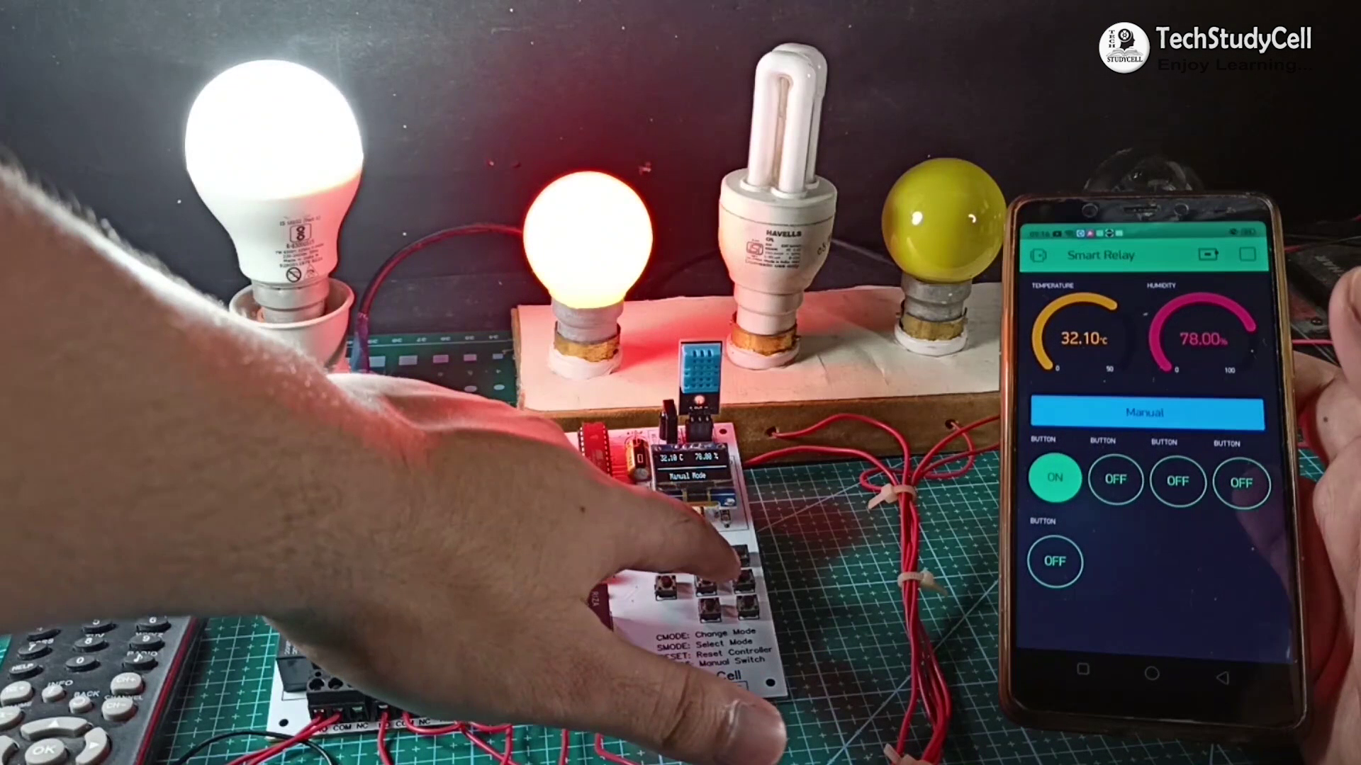
1. Manual Mode:
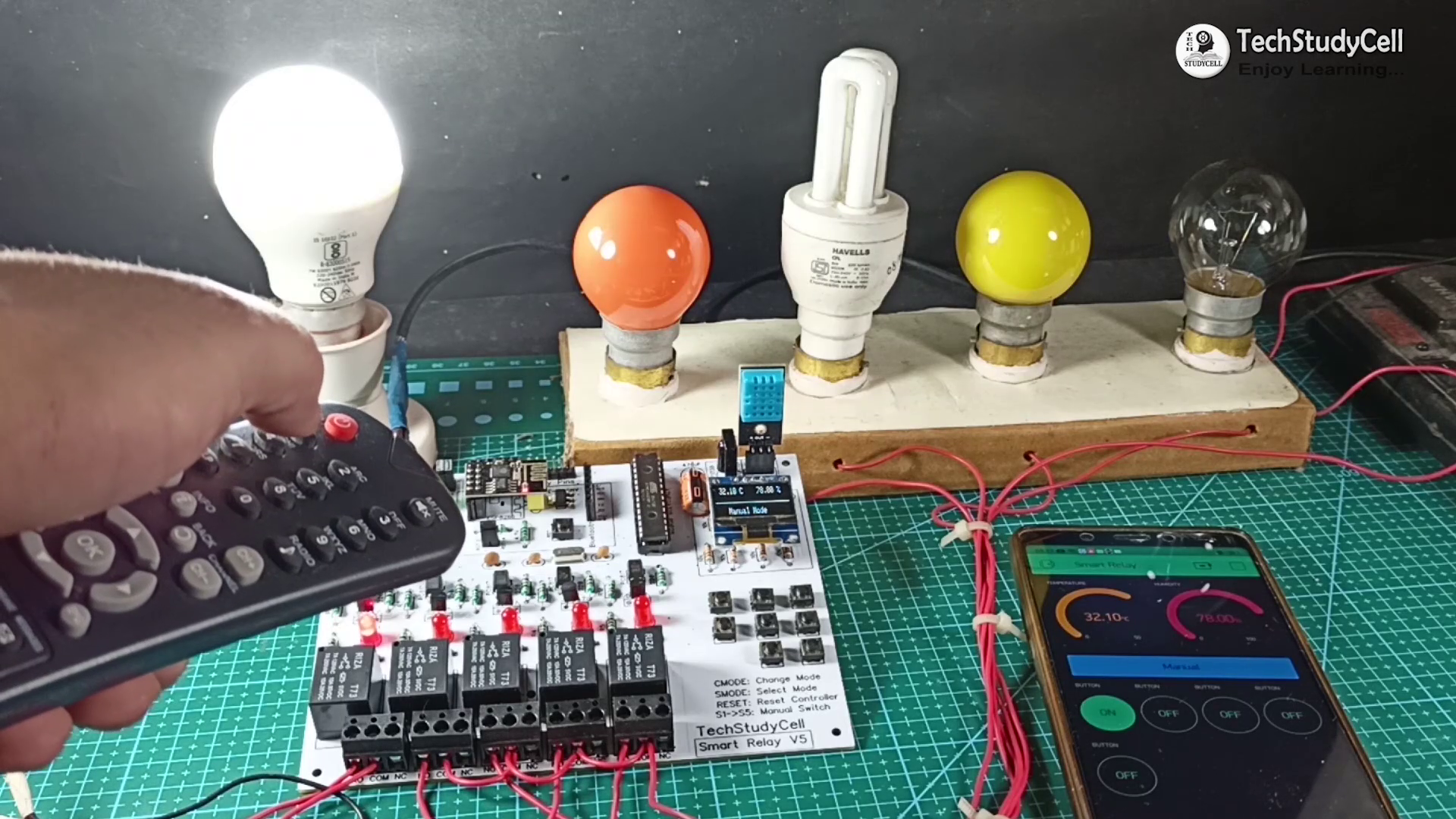
In manual mode, you can control the relay module manually from push buttons, smartphone & IR remote.
2. Auto Mode:
In auto mode, the DHT11 sensor and LDR will control the relay module as per the room temperature and ambient light.
In both modes, you can monitor the real-time status, temperature, humidity from the Blynk App.
WiFi Control From Blynk App
Here I have used ESP01 and Blynk app to control the relay module from the smartphone through the internet.
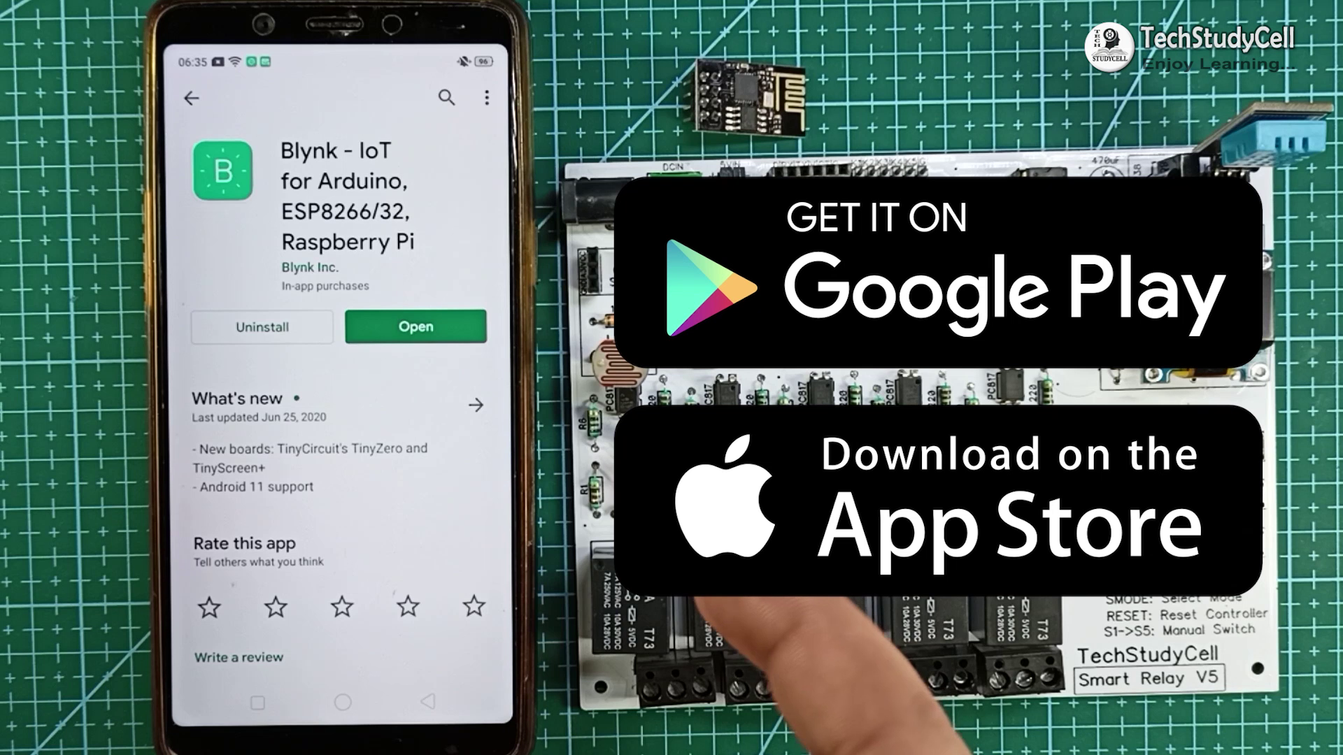
You can download the Blynk App from Google Play Store or App Store. I have explained the configuration in later steps.
As ESP01 works in 3.3V, so I have used the ASM1117 3.3V regulator to drop the voltage to 3.3V.
You can control the 5 home appliances from the smartphone from anywhere and also monitor the real-time status in the Blynk App.
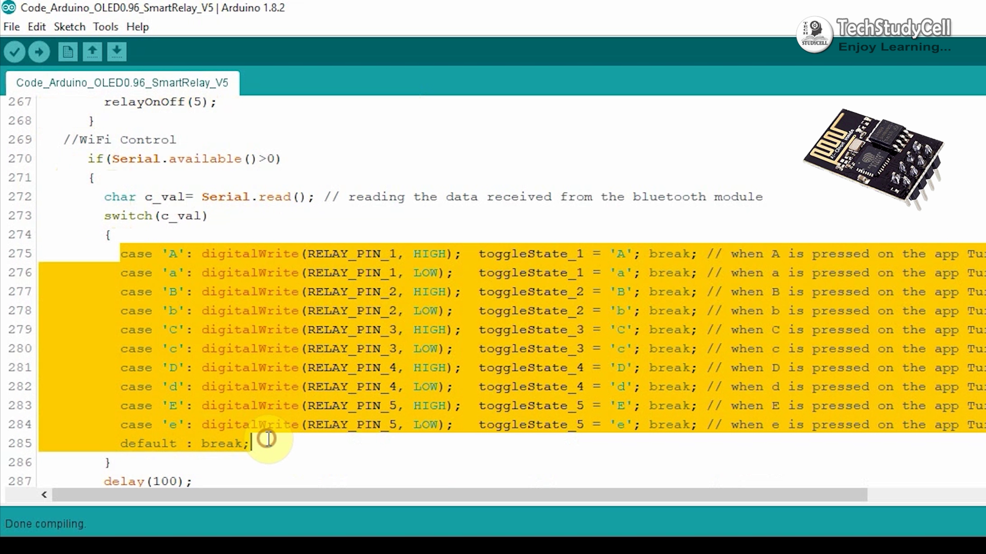
I have explained the code in the tutorial video.
Infrared Control From TV Remote
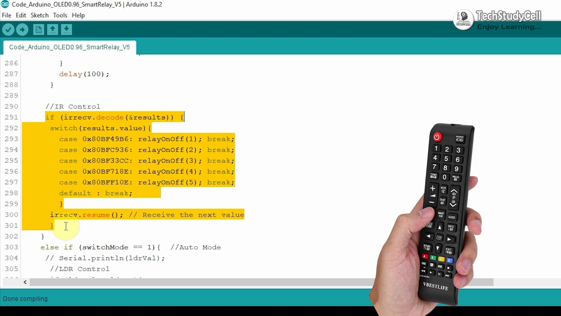
Here I have used the 1738 Infrared receiver IC to control the relay module from the TV remote.
You can use any infrared remote but you have to get the respective Hex codes of the remote buttons and modify the code accordingly.
You can refer to the embedded video where I have explained how you can easily get the hex code from the TV remote button. You can use any unused button from the remote to control the home appliances.
Manual Switch Control
The Relay module also can be controlled manually from the push buttons fitted on the PCB.
There are 5 push buttons S1, S2, S3, S4, S5 to turn on, and turn off the Relay1, Relay2, Relay3, Relay4, Relay5 respectively.
And there is a SMODE button to turn off all the relays at a time. I have explained the functionality of the circuit in the tutorial video.
You can use the Reset button to reset both microcontrollers.
Temperature Control (Auto Mode)
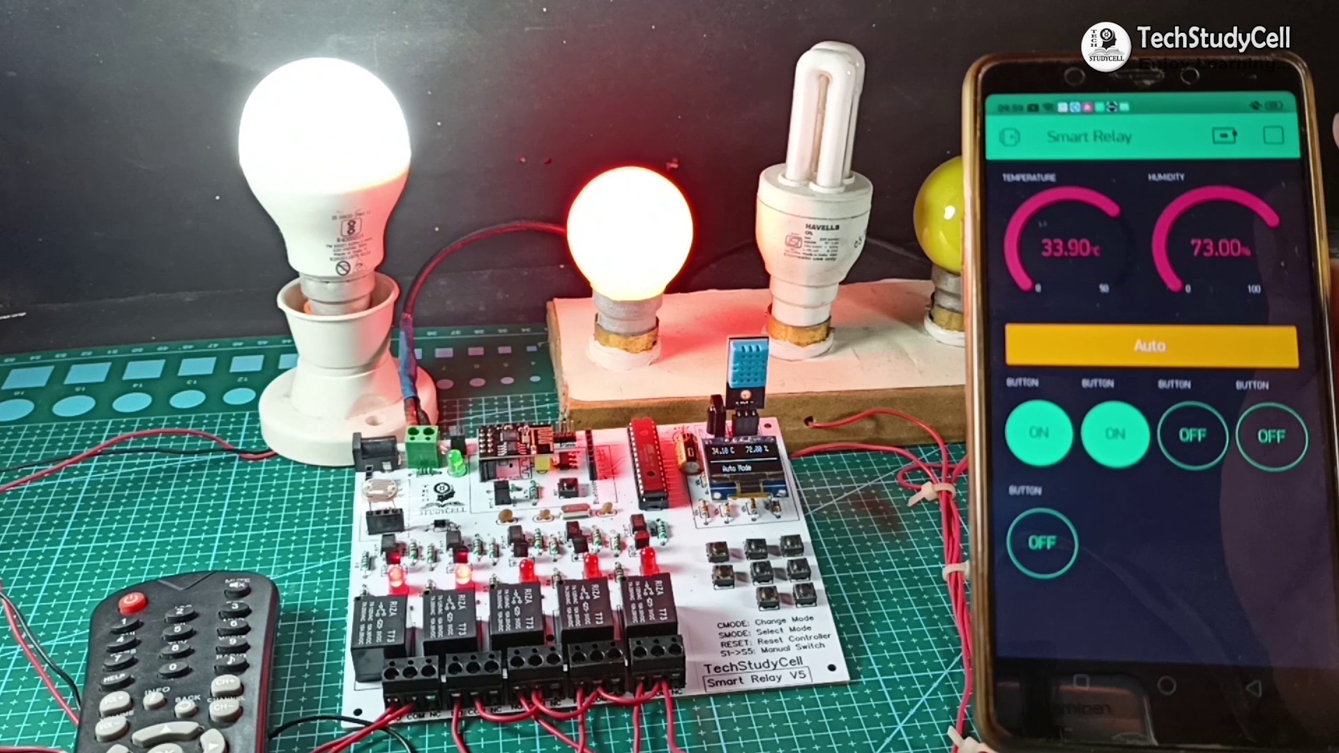
In Auto mode, this smart relay module can be controlled by pre-defined room temperature and sunlight. It has a DHT11 temperature and humidity sensor sense the temperature and humidity after every 2-second interval.
When the temperature crosses the predefined max temperature value mentioned in the Arduino code the relay-1 and relay-2 turns on.When the temperature becomes lower than the predefined min temperature value mentioned in the Arduino code the relay-1 and the relay-2 turns off.
LDR Control (Auto Mode)
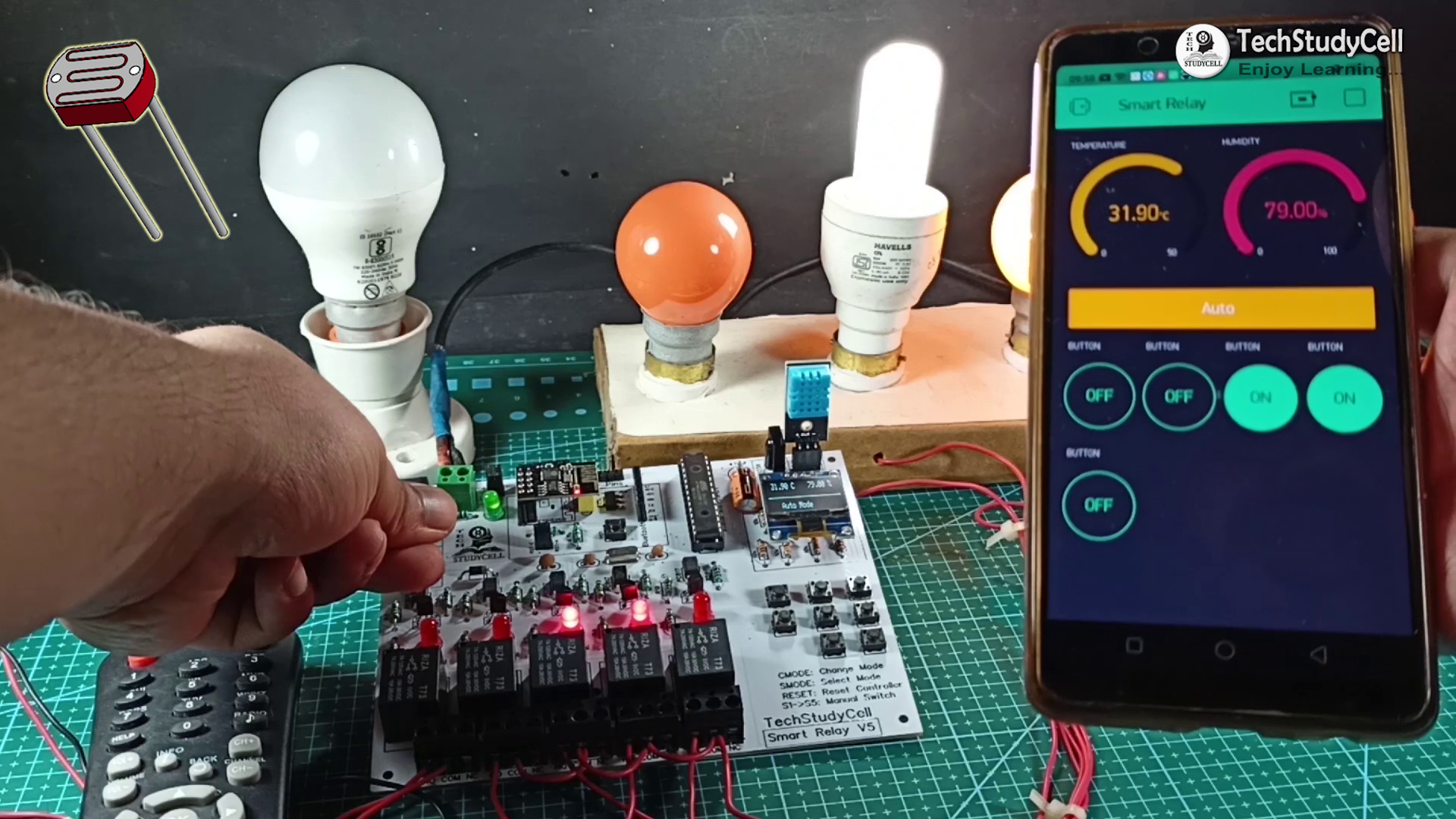
An LDR is fitted on the PCB to sense the ambient light. It acts as a dark sensor.
When the brightness level becomes below the predefined value the Relay-3 and Relay-4 turns on.
When the brightness level crosses the predefined value the Relay-3 and Relay-4 turns off.
Please refer to the Embedded video on the top for better understanding.
Install & Configure the Blynk App
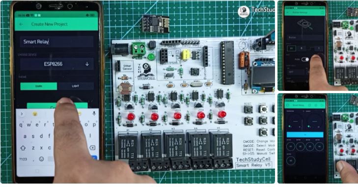
Install the Blynk App from Google play store or App store then add all the required widgets to control the relay module and monitor the temperature and humidity. I have explained all the details in the tutorial video.
I have used the 5 Button widgets to control the 5 relays, 1 Style Button to see the current mode, and 2 Gauge widgets to monitor the temperature and humidity.
Designing the PCB
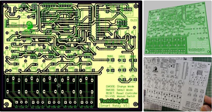
To make the circuit compact and give a professional look, I have designed the PCB after testing all the features of the smart relay module on the breadboard.
You can download the PCB Gerber file of this home automation project from the following link:
https://drive.google.com/uc?export=download&id=1-orn4hASKFz8IZVsRcmPziN28wmy3usM
Order the PCB
After downloading the Garber file you can easily order the PCB
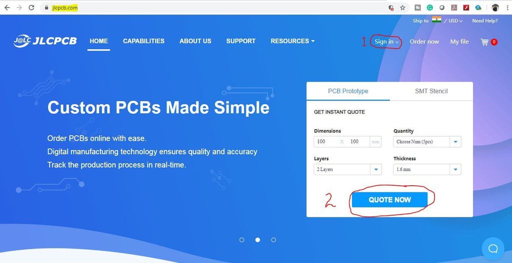
1. Visit https://jlcpcb.com and Sign in / Sign up
2. Click on the QUOTE NOW button.
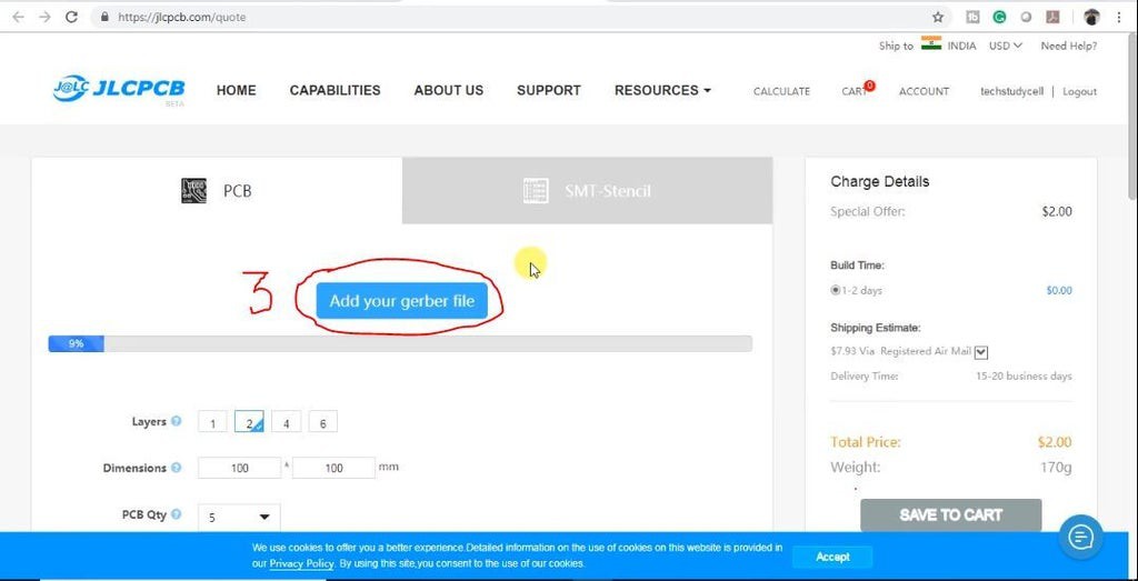
3 Click on the "Add your Gerber file" button.
Uploading the Gerber File and Set the Parameters
Then browse and select the Gerber file you have downloaded.
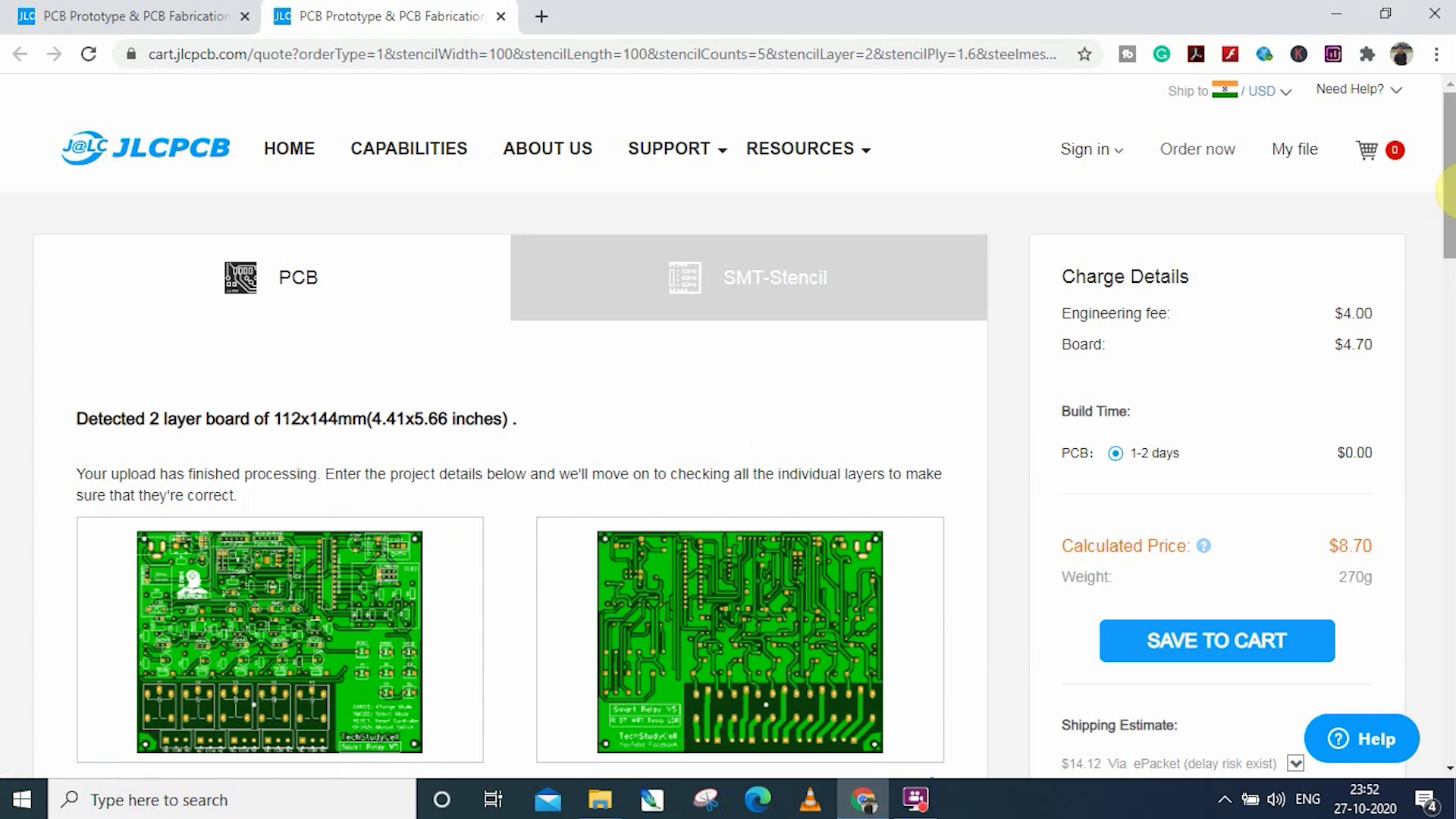
4. Set the required parameter like quantity, PCB color, etc
5. After selecting all the Parameters for PCB click on SAVE TO CART button.
Select Shipping Address and Payment Mode
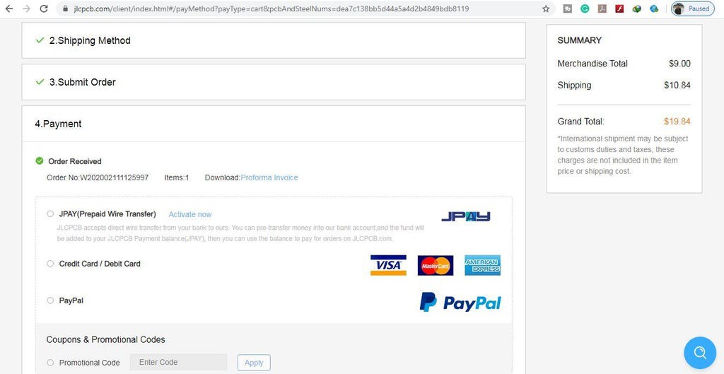
8. Submit the order and proceed for the payment.
You can also track your order from the JLCPCB.com.
My PCBs took 2 days to get manufactured and arrived within a week using the DHL delivery option.

PCBs were well packed and the quality was really good at this affordable price.
Solder All the Components

After that, I have soldered all the components as per the circuit diagram.
Then connect the Atmega328P microcontroller, DHT11 sensor, LDR & OLED Display.
Program the Atmega328 Microcontroller

1. Connect the USB to Serial interface board (FTDI232).
2. Download the Arduino sketch. (Attached)

3. Change the Max and Min Temperature and LDR value as per your requirements.
3. Select the Arduino UNO board and proper PORT. Then upload the code.
In Auto Mode, at Max temperature, Relay1 & Relay2 will turn ON, and at Min temperature, Relay1 & Relay2 will turn OFF.
Relay3 & Relay4 will be controlled by the LDR value.
Program the ESP01

You can use both Arduino UNO and TDI232 to program the ESP01 board.
You can refer to my old tutorial video on how to program the ESP01 board.
1. Download the Code for ESP01. (Attached)

2. Type the Blynk Auth token, WiFi Name, WiFi Password.
3. Select the ESP8266 board and proper PORT. Then upload the code.
I have explained the code in the tutorial video.
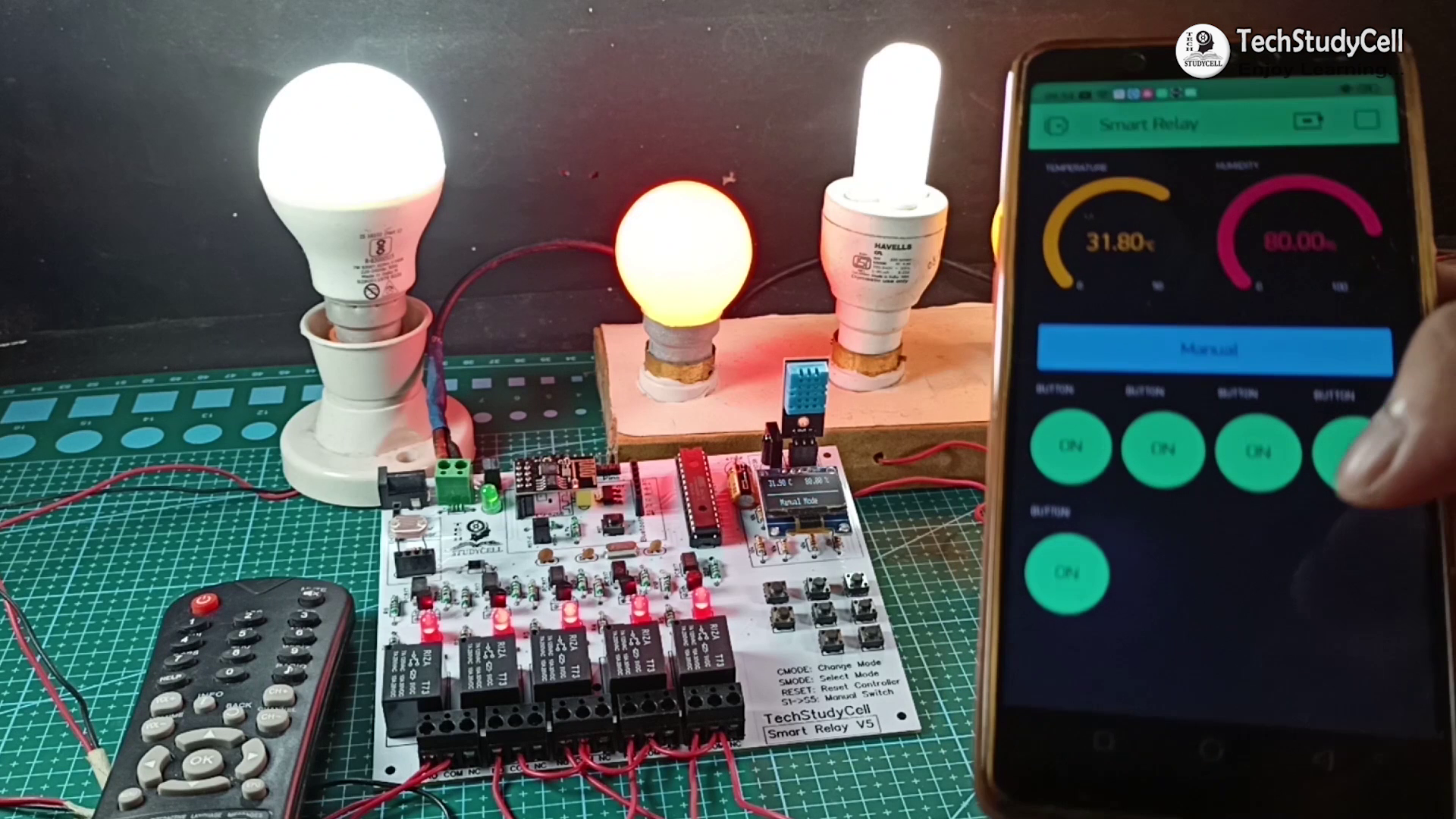
Connect the Home Appliances

Connect the 5 home appliances as per the circuit diagram. Please take proper safety precautions while working with high voltage.
Connect 5Volt DC supply to PCB as shown in the circuit. (I have used my old mobile charger)
Turn ON the Supply

Turn on the 110V/230V supply and 5V DC supply.
Now you can control your home appliances in a smart way.
I hope you have liked this home automation project. I have shared all the required information for this project.

I will really appreciate it if you share your valuable feedback, Also if you have any query please write in the comment section.
Thank you & Happy Learning.