 Hulk
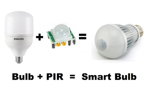
HulkDIY - IR Module
Components Used
-----------------------
For this project we need:
- 1 x LM358 IC
- 1 x 10K Potentiometer
- 1 x LED
- 1 x IR LED
- 1 x PhotoDiode
- 1 x 100Ω Resistor
- 1 x 100kΩ Resistor
- 1 x 220Ω Resistor
IR LED
-----------
Now lets talk about the three main components of this module:
1. IR Transmitter [IR LED]
-----------------------------------
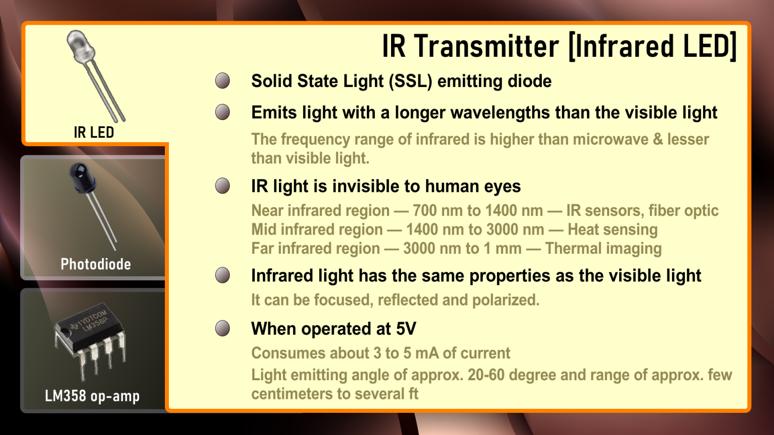
The IR LED (Infrared Light-Emitting Diode) is a SSL (Solid State Light) emitting diode that emits light with a longer wavelengths than the visible light. (The frequency range of infrared is higher than microwave and lesser than visible light). IR light is invisible to human eyes as its wavelength ranges between 700nm to 1mm. Everything which produce heat, emits infrared light, a very common example is the human body and fire. Infrared light has the same properties as the visible light, it can be focused, reflected and polarized. The appearance and operation of an IR LED is same as a common LED. When operated at 5V, the IR transmitter consumes about 3 to 5 mA of current. Depending upon the Transmitter and Manufacturer, IR LEDs can have light emitting angle of approx. 20-60 degree and range of approx. few centimeters to several ft (Some transmitters have the range in kilometers). Since the human eye cannot see the infrared radiations, it is not possible for a person to identify if an IR LED is working or not. The simplest way to view infrared light is by using a remote control while looking through a camera. If the infrared LED is working, it will appear on the digital camera's viewfinder as a purple glow. Unlike LEDs that project parts of the visible light spectrum, IR LEDs are not used to provide lighting. They are, instead, most commonly used in various signal transferring systems, such as in remote controls, night-vision cameras and other devices. IR LED’s are commonly used in conjunction with the IR receiver to support a wireless communication between 2 or more devices.
2. IR Receiver [PhotoDiode]
------------------------------------
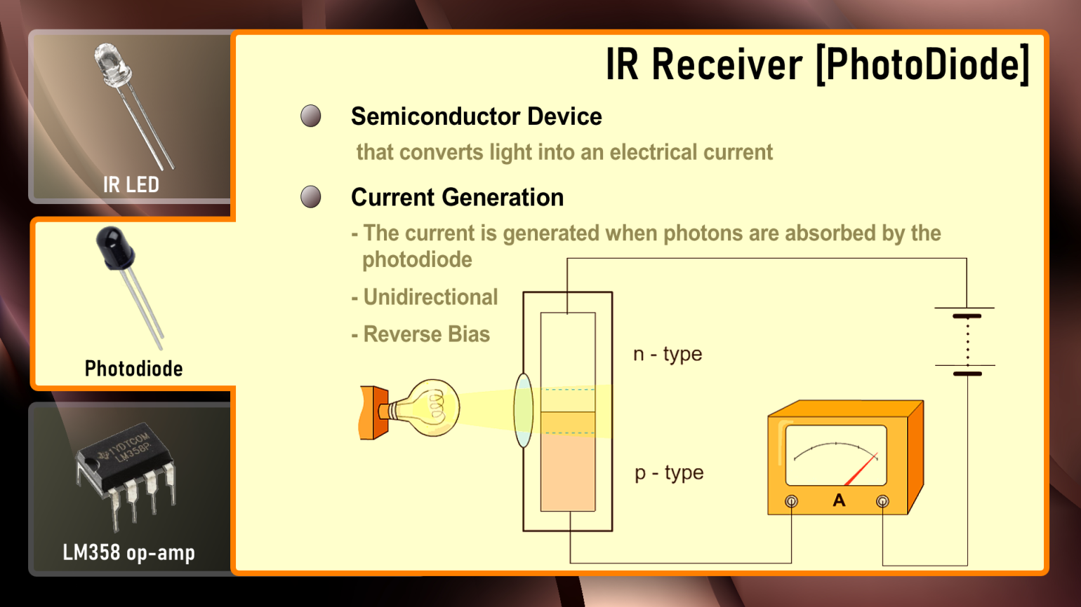
A photodiode is a semiconductor device that converts light into an electrical current. The current is generated when photons are absorbed by the photodiode similar to a Light Dependent Resistor (LDR), means it has very High Resistance in absence of light and the Resistance become low when light falls on it. However, unlike the LDR which is analogue and bidirectional, Photodiode is a unidirectional semiconductor which has a P-N junction and operates in Reverse Bias (means it start conducting the current in reverse direction when Light falls on it). Photodiodes can only do two values: either on or off.
Photodiodes also looks like a LED, with a Black color coating on its outer surface. Different types of IR receivers exist based on the wavelength, voltage, package, etc. When used in an infrared transmitter – receiver combination, the wavelength of the receiver should match that of the transmitter.
3. LM358 IC
----------------
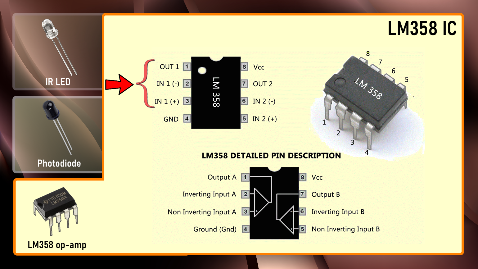
LM358 is a dual operational amplifier (Op-Amp) IC, integrated with two op-amps powered by a common power supply. In this circuit we are using it as a voltage comparator. The LM358 has two independent voltage comparators inside it, which can be powered by single pin, so we can actually build two IR sensor modules using this IC. In this tutorial I will only use one comparator, which have inputs at PIN 2 and 3 and output at PIN 1. The voltage comparator has two inputs, one is inverting input (PIN 2) and second is non-inverting or in-phase input (PIN 3). When voltage at non-inverting input (positive pin) is higher than the voltage at inverting input (negative pin), then the output of comparator (PIN 1) is High. And if the voltage of inverting input (negative pin) is Higher than non-inverting end (positive pin), then output is LOW. PIN 4 is the negative power supply (when dual power supply operates) or ground (when single power supply operates)....Read more »

 Sagar 001
 Andrew Sowa
 t.oster92
https://www.youtube.com/watch?v=_M8FQIPi1qk&feature=youtu.be