 Peter Wasilewski
Hi!
That is why I’ve been working on something else. Having remembered how difficult upgrading 12 controllers mounted on a robot was, I decided to write a custom CAN bootloader. I didn’t want to use the built in CAN bootloader, because it cannot be customized and as far as I know it has some bugs. I found some very helpful information online, as I was not quite familiar with the booloader convention:
-Josh's Pieper's blog: https://jpieper.com/2020/01/24/can-bootloader-for-moteus-r4-x/
-Kevin's Cuzner's blog: http://kevincuzner.com/2018/06/28/building-a-usb-bootloader-for-an-stm32/
After reading these guys’ work and going through some source codes I had a fundamental understanding of the whole bootloading process.
The code was tested on a previous version of my controller and a f476 nucelo board serving as a USB <=> CAN converter. The converter is used as a translator between the serial data sent from the computer and CAN bus. An additional byte in the serial frame indicates a CAN command ID. The rest is just data.
The bootloading procedure:
When the slave device is in bootloader mode it can receive a few different CAN commands. The host computer executes a python script, which first opens a firmware file and sends a command to the destination device about the size of memory to erase. After a successful erase process the slave device sends an "ok" message and the process of firmware download is started. The script sends chunks of firmware to the slave device. After a preset number of bytes is sent, the computer script sends a CRC code and pauses. If the code matches with the slave's internally computed code another "ok" message is sent to the master device. The whole process repeats until the end of the *.bin file is reached. In the end the computer transmits a reset command, and the new firmware is started.
Bootloader mode is entered only when the soft reset occurred and the master device sent an appropriate command within a 1,5 second time window. For now any other reset causes an immediate jump to the user’s code. I find this quite useful, because when the drivers are powered on I want them to start executing the firmware without any delay, and the bootloader mode can be easily entered through a special CAN frame resulting in soft reset. The bootloader is still in development stage, as I'm still waiting for the PCBs.
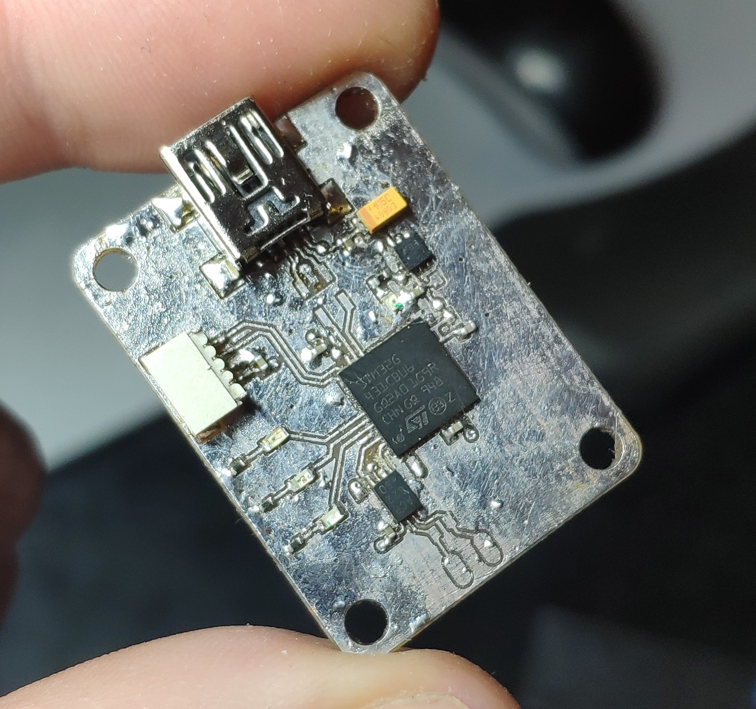
I came across one mistake on the CAN<=>USB converter PCB. The new G4 series is capable of using boot0 pin as any other GPIO. Without much thinking, I remmaped CAN FD interface to the PA8 (boot0) /PA9 pins. This resulted in entering the bootloader mode each time the device was powered on and a normal startup was not possible (the rxd pin of the transceiver is pulled high when the bus is recessive). A quick fix was an NPN transistor between the rxd and gnd, with a small capacitor on it's base connected to the 3.3V rail. When the voltage is applied the empty capacitor is draining current and thus opening the NPN transistor which, for a really small period of time, shorts the PA8 pin to the ground. When the capacitor is charged up the transistor opens, and does not interfere with the communication process. In the second revision I'm just going to use the dedicated standby pin of the transceiver ;)
CNC milling machine
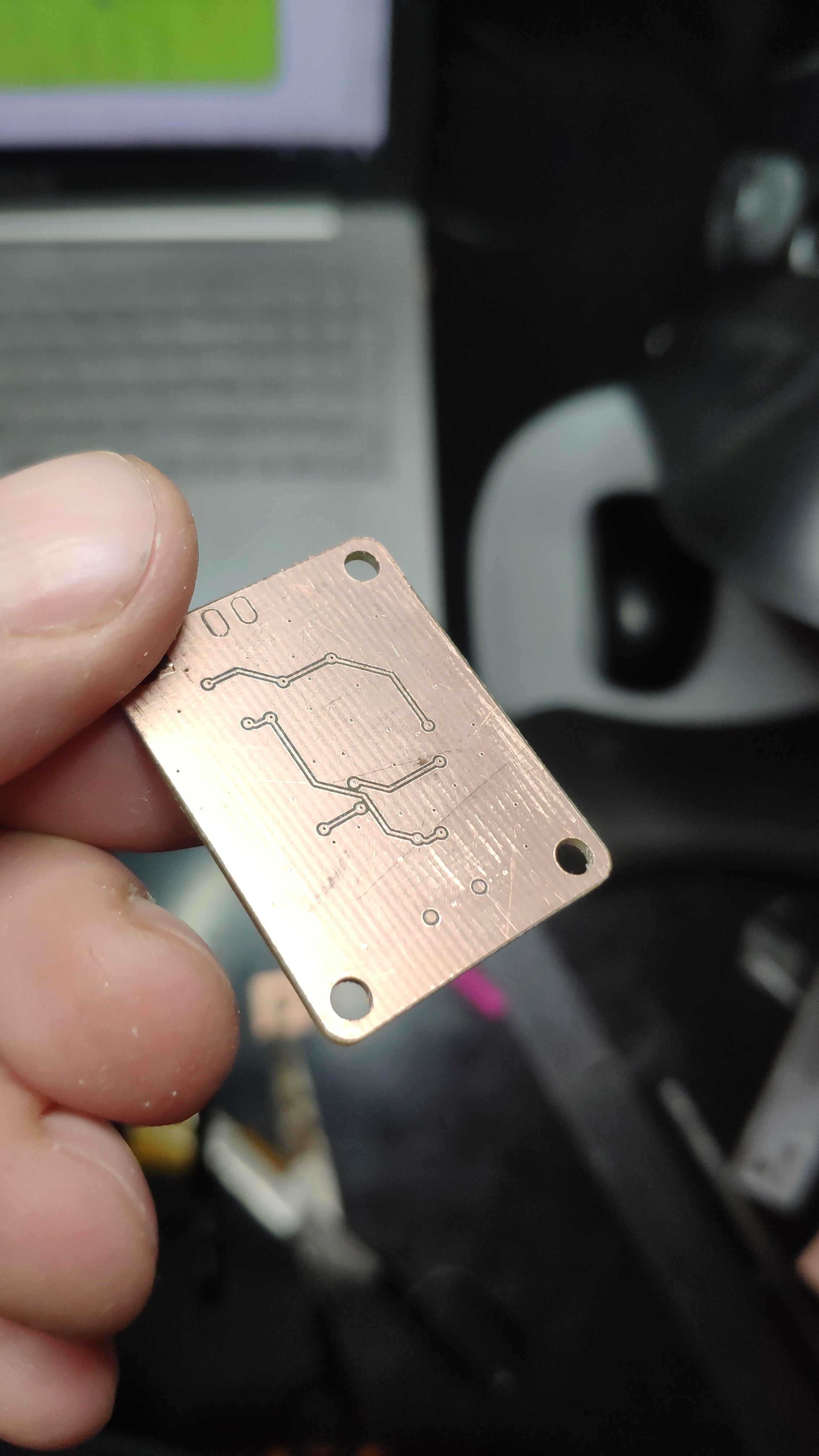
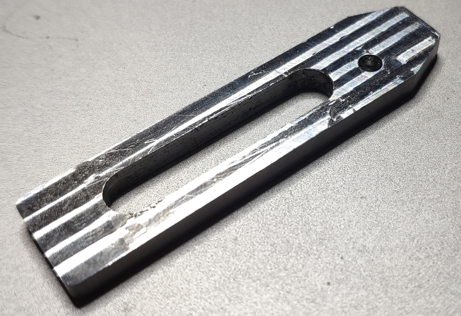
Another thing I wanted to mention is the cnc milling machine I’ve been working on for a couple months now. It was meant to mill small parts for my walking robots, mostly aluminum and plastics. The working area is about 300x300x130mm, so I’m able to mill even medium size parts such as robot’s leg fragments. For now I have only tested it in laminate and PA9 aluminum (which is an excellent material for milling). I still have to replace the supported shafts on the Z axis with linear rails, but I’m quite happy with the results right now. Below you can see a two layer board of the CAN<->USB converter, and an aluminum clamp.
The machine itself :
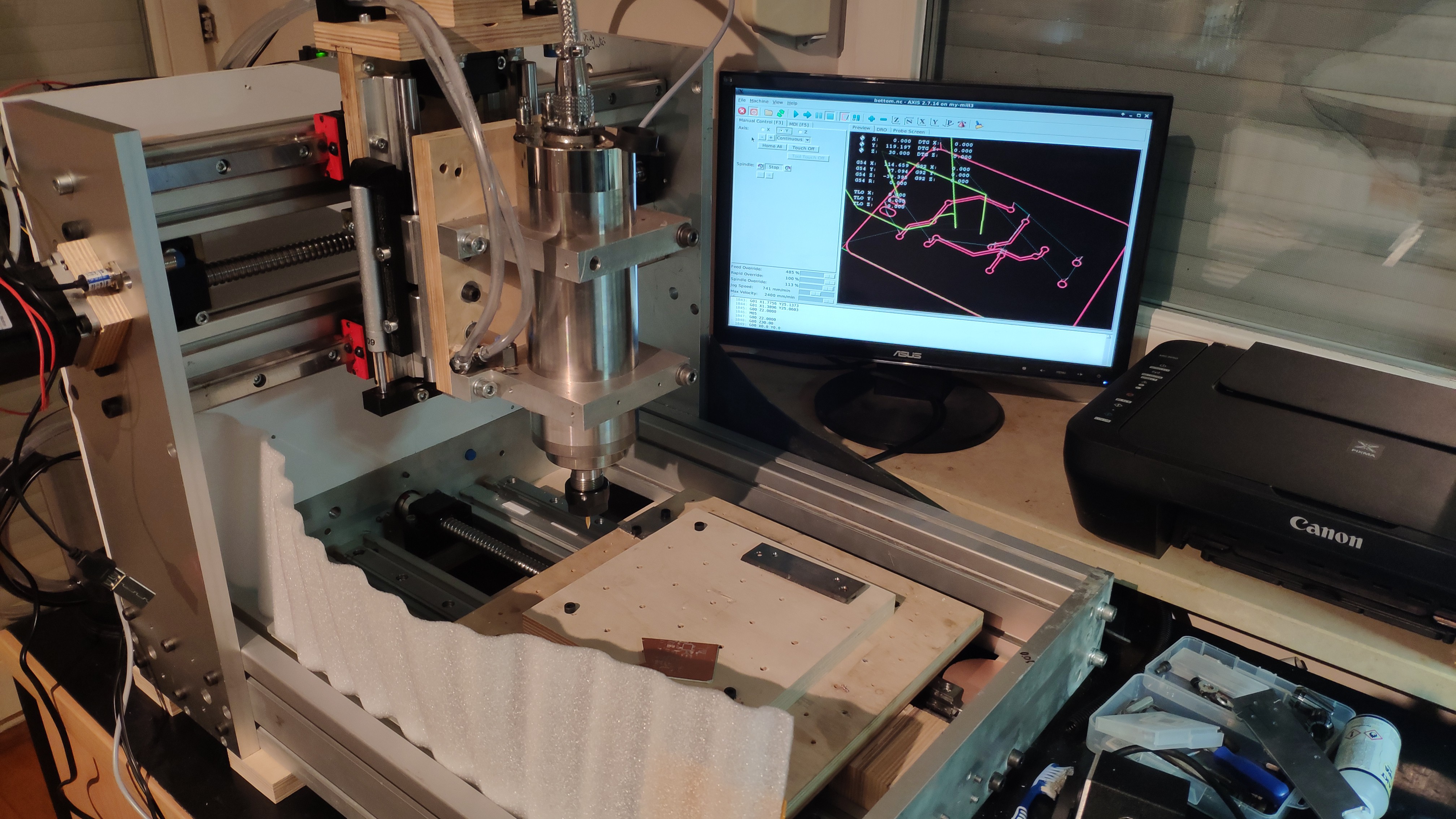
There is still much work to do, such as protection covers for the ball screws and linear rails as well as some housing for the whole device. These plywood parts are going to be replaced with aluminium plates, after this whole quarantine situation ends. For now it does the job.
More about the machine: https://pwwprojects.blogspot.com/
Discussions
Become a Hackaday.io Member
Create an account to leave a comment. Already have an account? Log In.