 Peter Wasilewski
Hi!
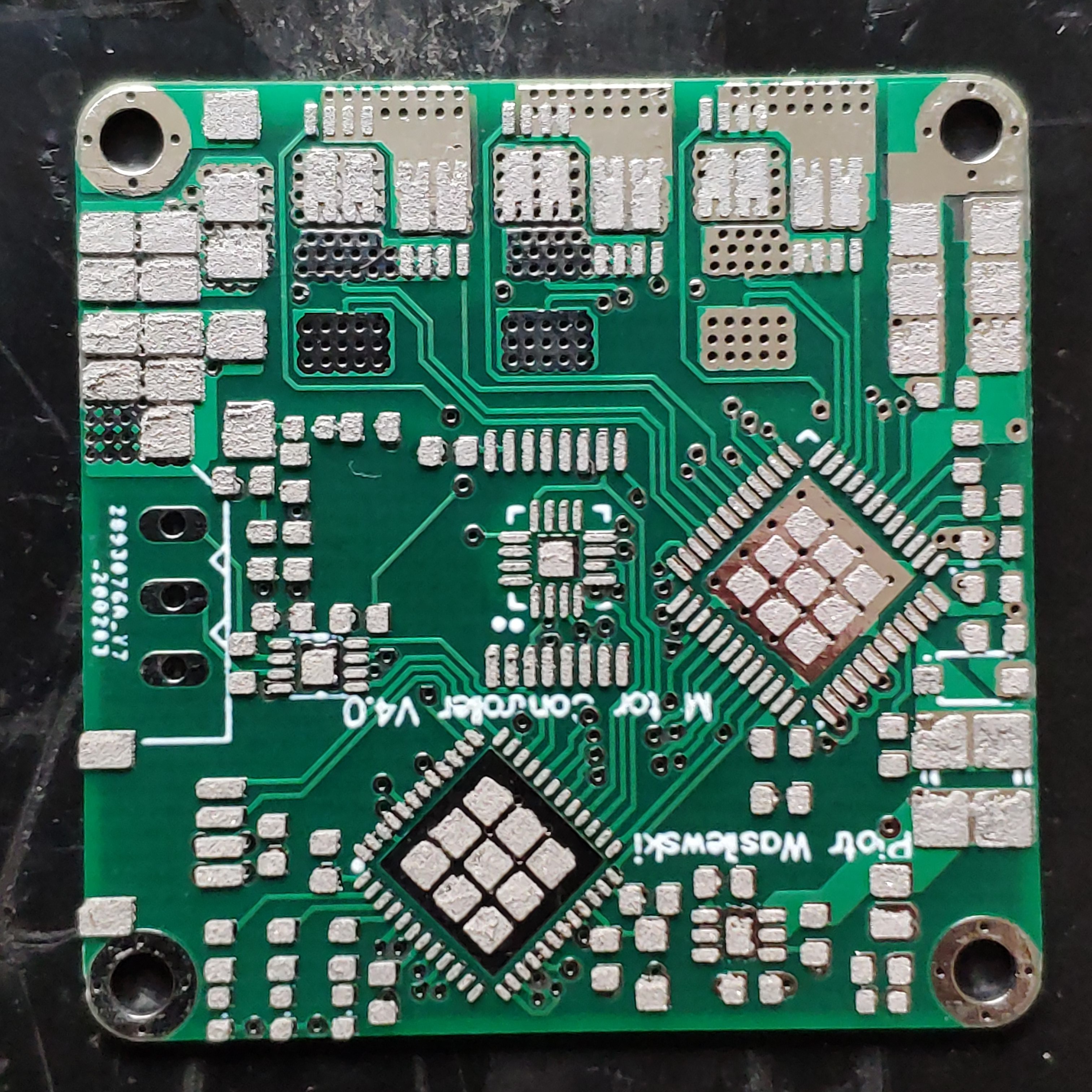
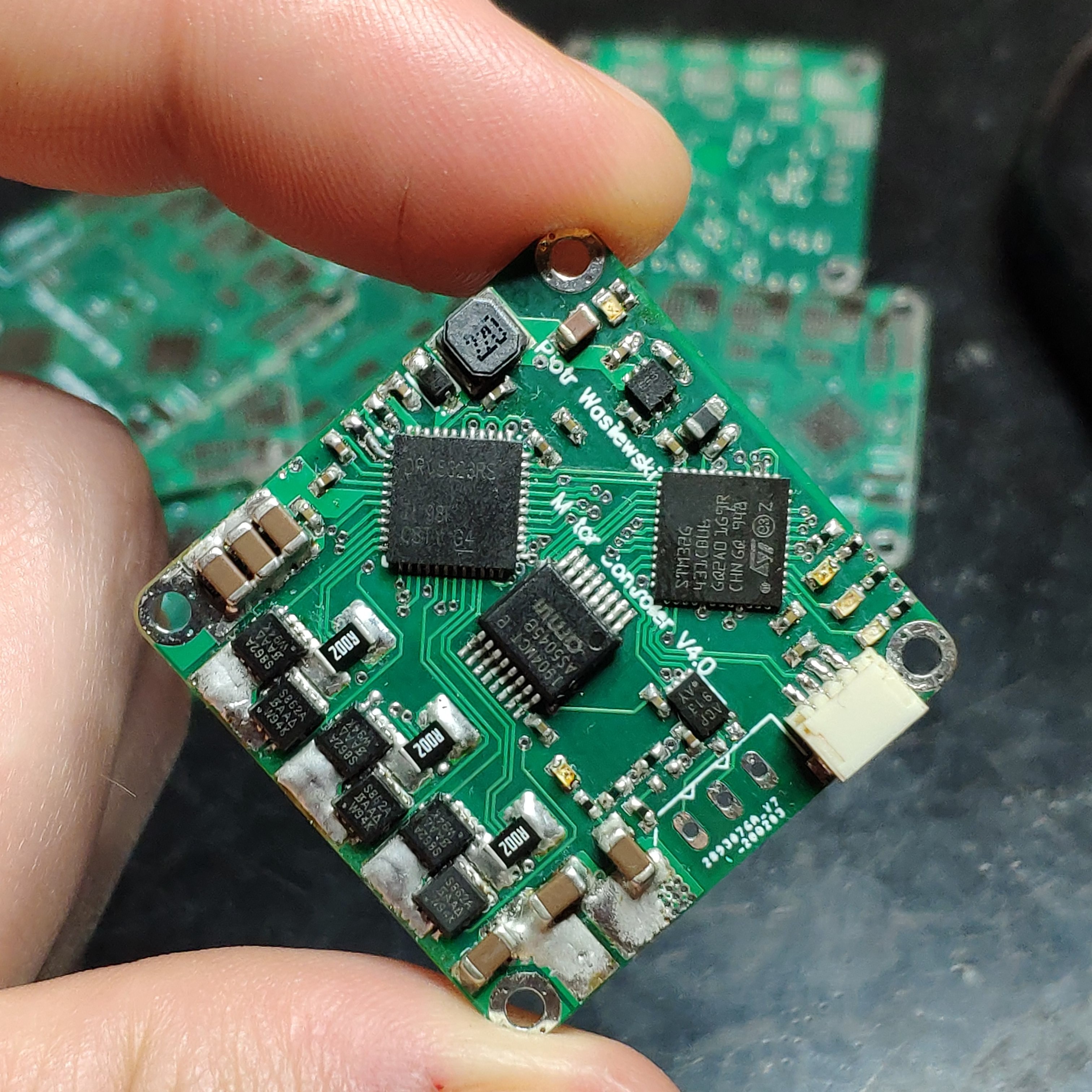
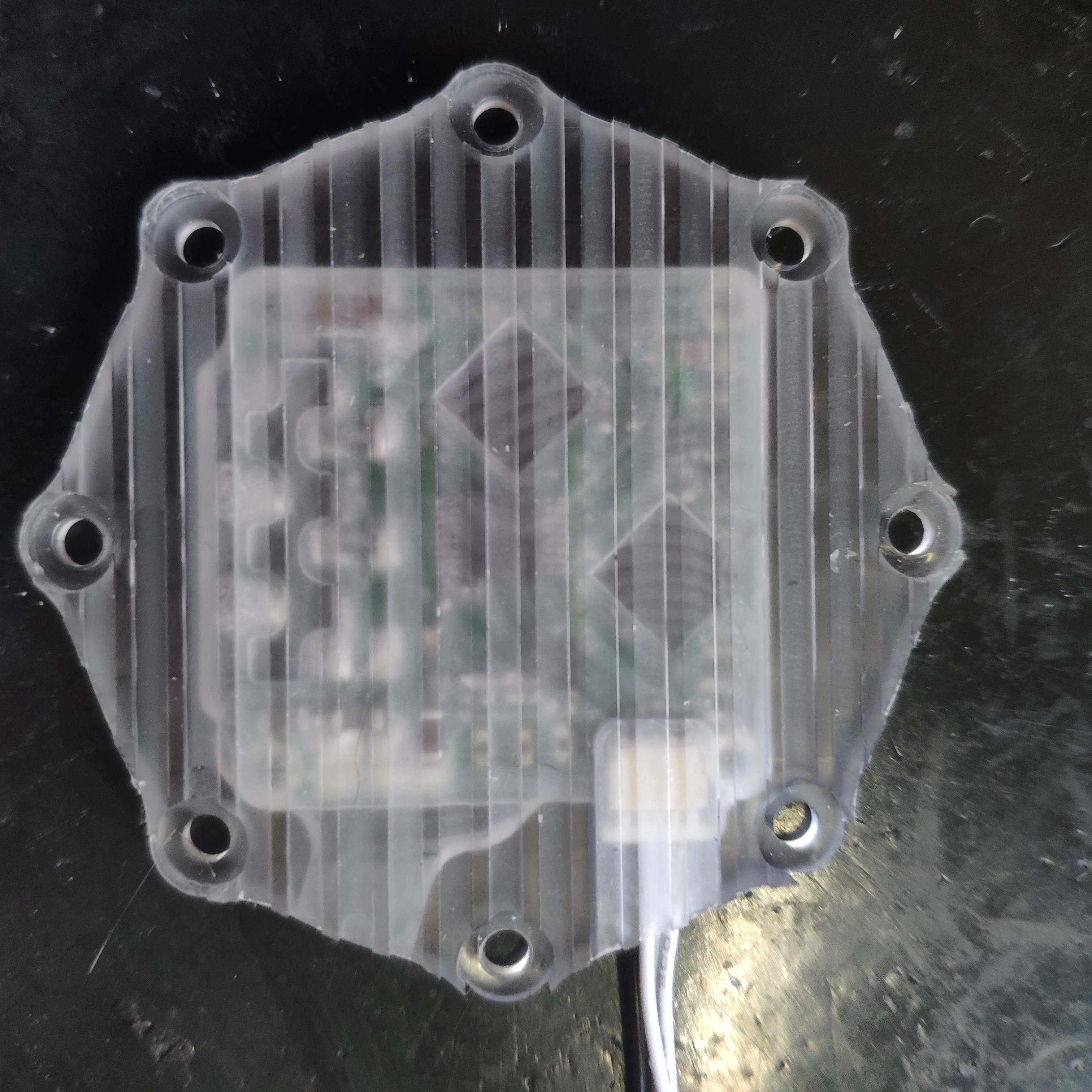
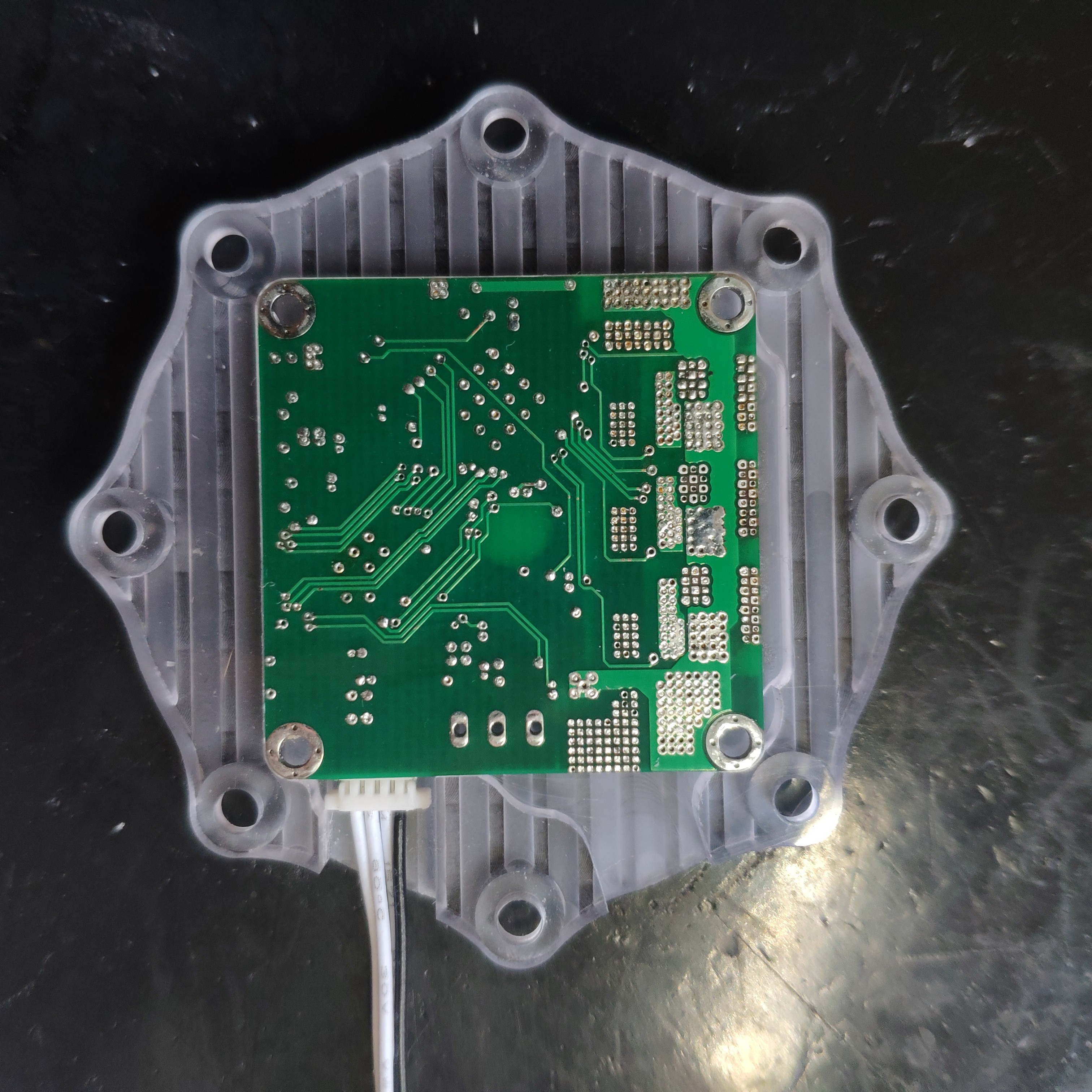
Finally the PCBs have arrived. I guess I imagined them a bit bigger, as I was surprised by how small they really are. The outline is just 33x33mm, so I will be able to fit it behind almost any of my smaller BLDC motors. Since I last wrote I've been working on the software of the controller. For now I'm able to perform some basic operations on the motor as spinning in the non-feedback mode (voltage mode) or current feedback mode. The controller is also able to do a magnet offset calibration as well as encoder non linearity calibration and save the calibration lookup table in flash memory. Though everything seems to work fine at first glance, I still get annoyed by the irritating sound coming from the motor. I even wrote a post on the TI forum (https://e2e.ti.com/support/motor-drivers/f/38/p/921831/3412724#3412724) but the issue is still unresolved. I will investigate it further someday, however right now I'm out of ideas.
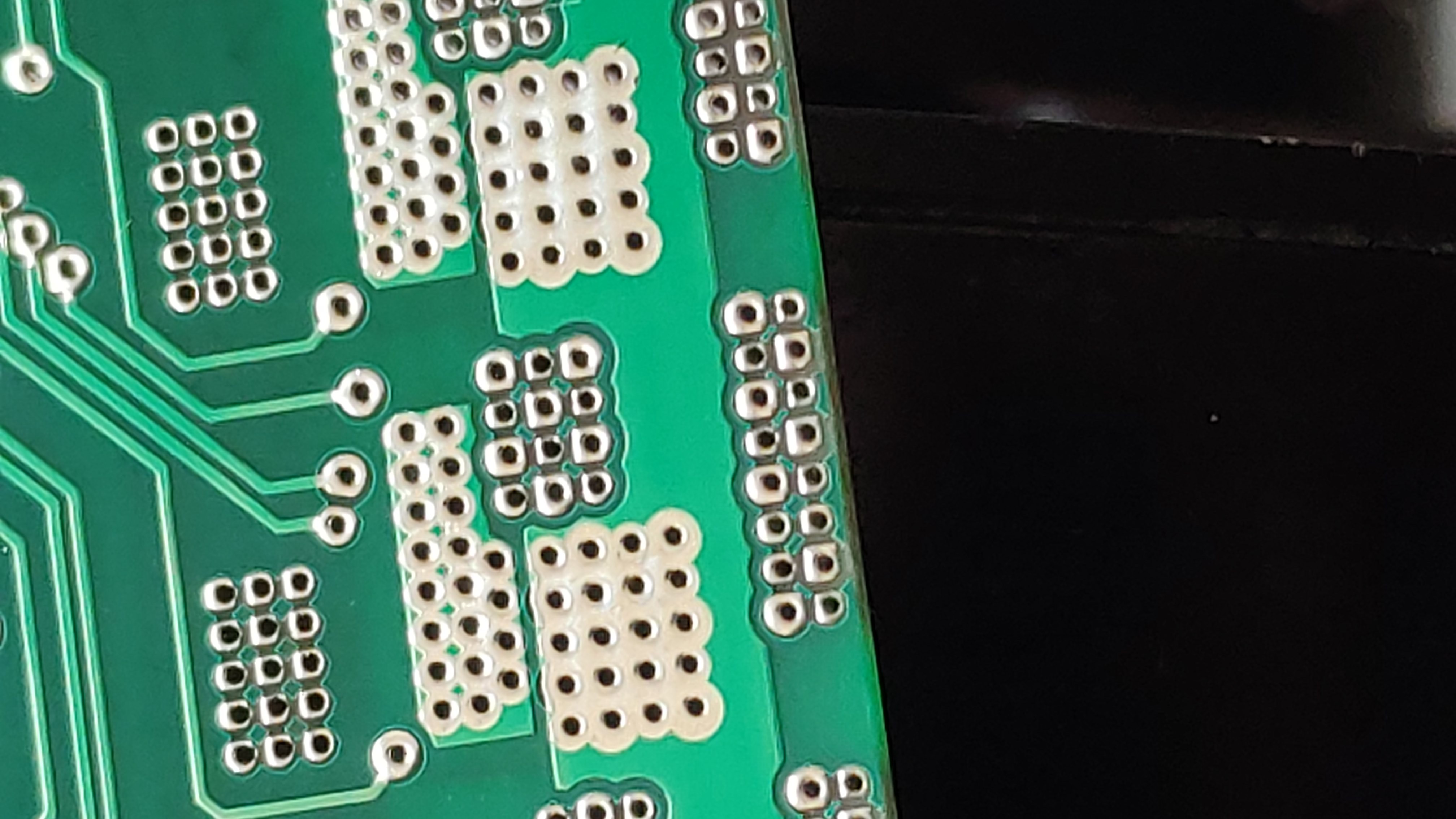
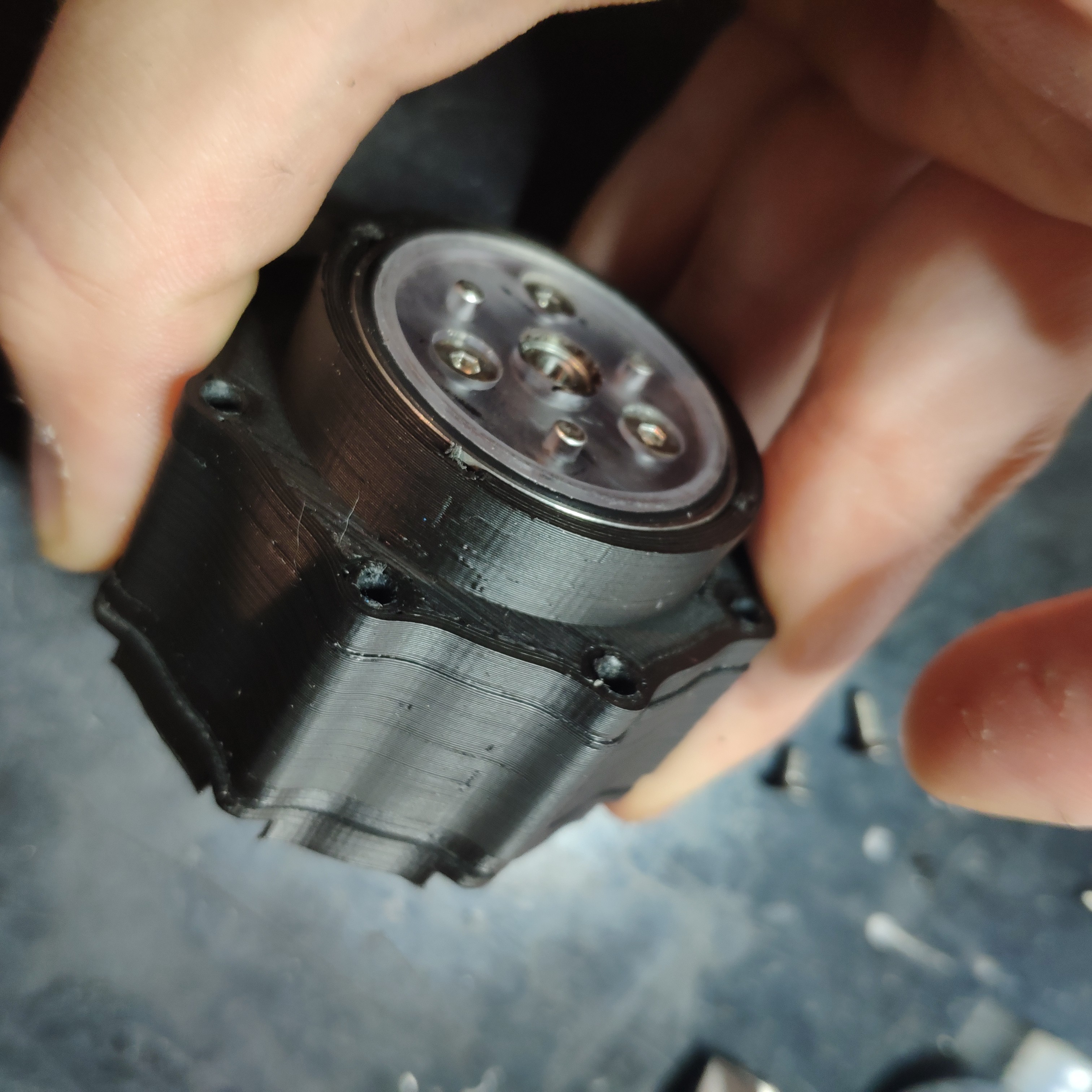
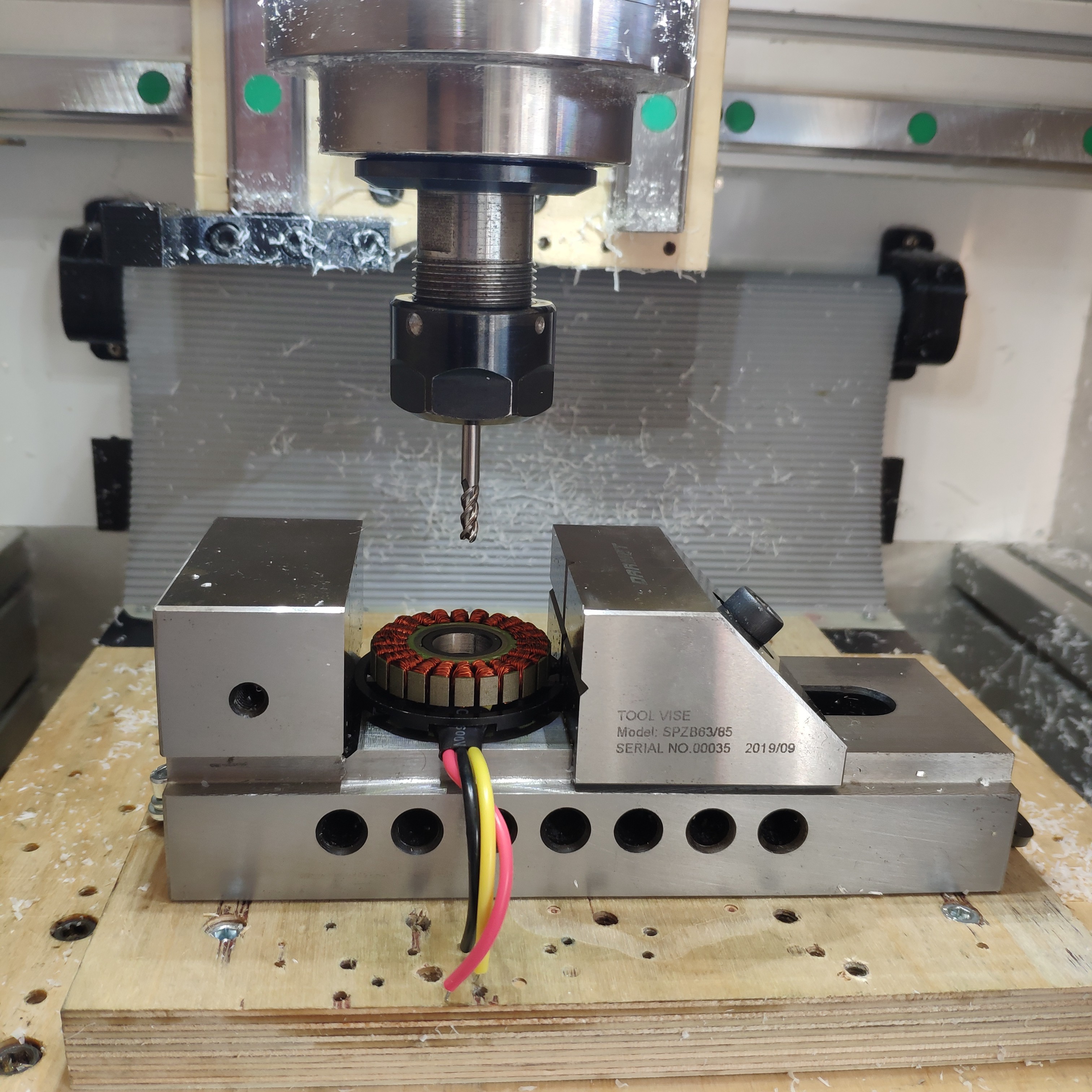
Right now I'm working on a mechanical casing and planetary gear for the motor module. I managed to mill some prototype parts and it looks promising, however I'll tell more when the first prototype is ready. The biggest issue for now is the backlash of the planetary gear extracted from cordless drill. On a 3d printed prototype, I get roughly 1.5* of backlash when the motor shaft is stalled. I believe I'll be able to take it down to 1* or less with a bit of precise machining. Even though it seems much when I remember that triple stage planetary reducer for a drill cost me about 5$ each I guess it is a decent outcome anyway. Below a few random photos from prototyping process:
When I'm ready with a fully machined prototype I'll write an update ;)
Discussions
Become a Hackaday.io Member
Create an account to leave a comment. Already have an account? Log In.