 andriy.malyshenko
Why mighty ATtiny?
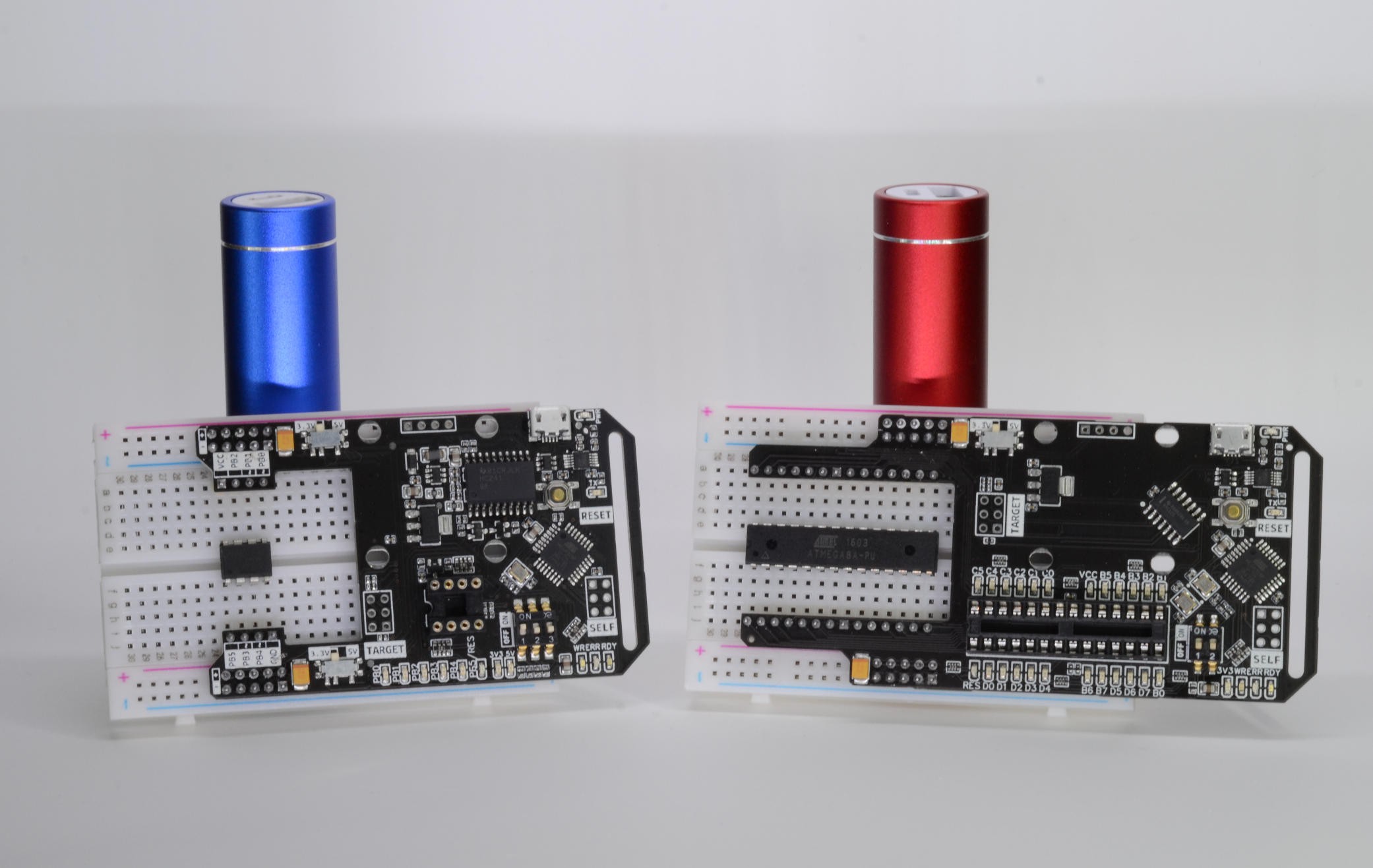
- It's dirt cheap
- It's quite capable
- It's just enough
- When it's not, it's challanging ;)
Why ATtiny Flasher?
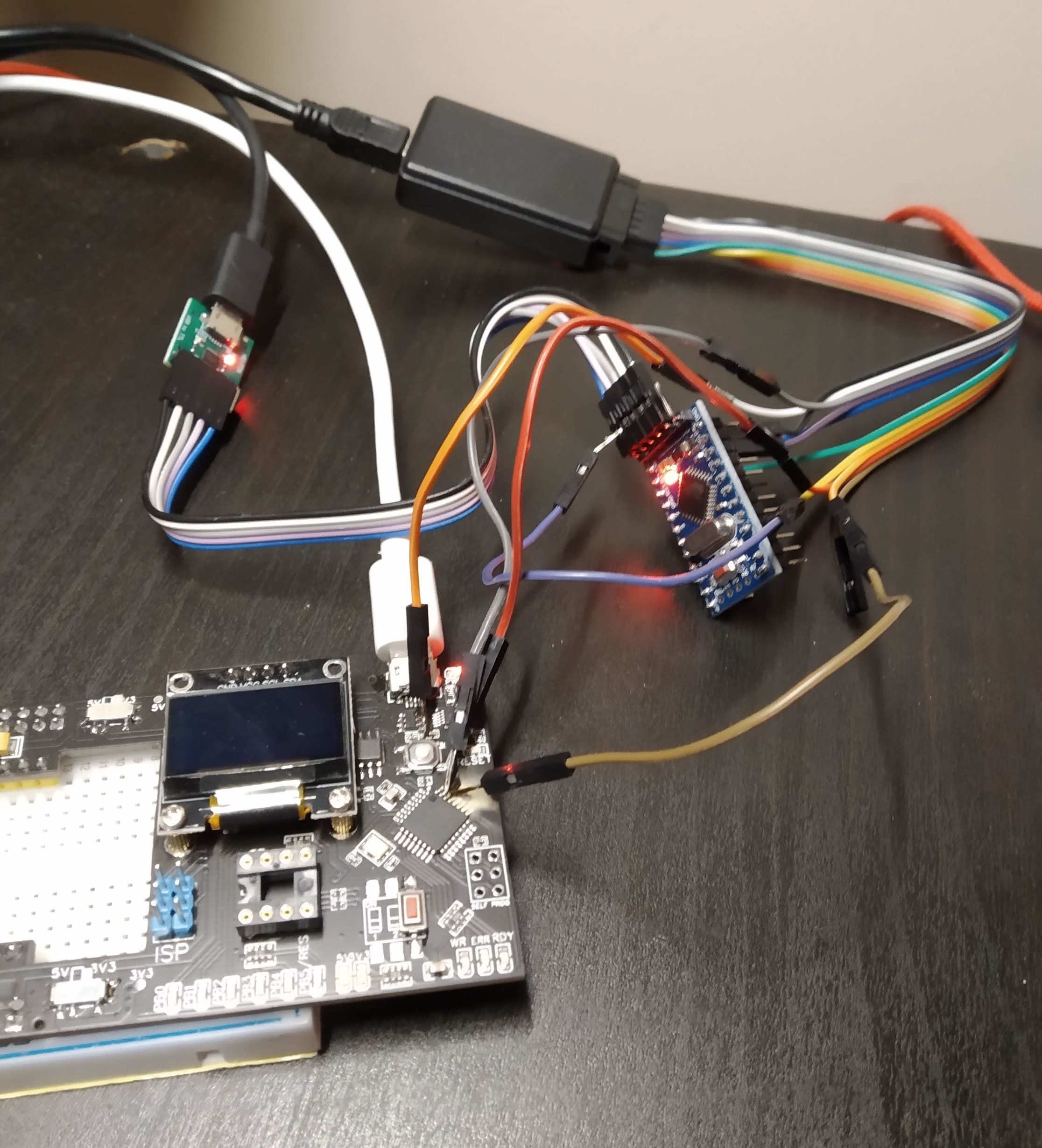
- Code, build, flash, test, code again, without interuption. Just like normal Arduino board
- Debug using Serial. Just like normal Arduino board
- All GPIOs visualized, see what's happening on the fly
- Sensor needs 3.3V, not 5V? Click, done!
Key features
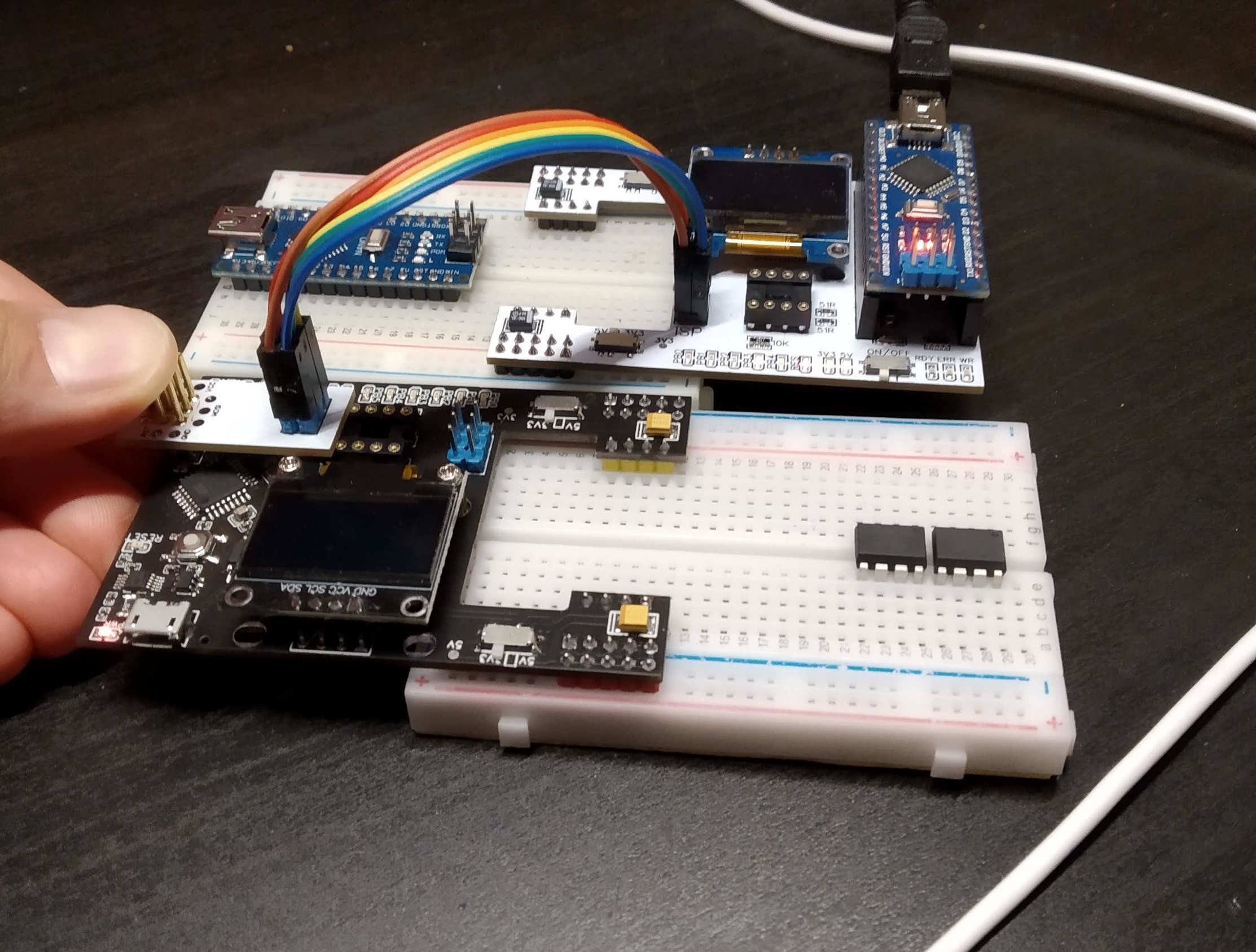
- Flashing using Arduino IDE, Platformio or any other IDE of your choice
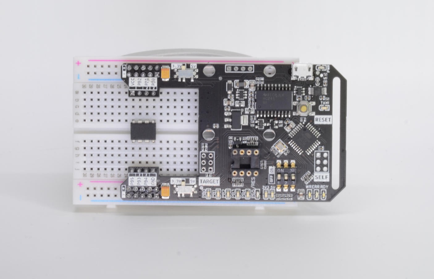
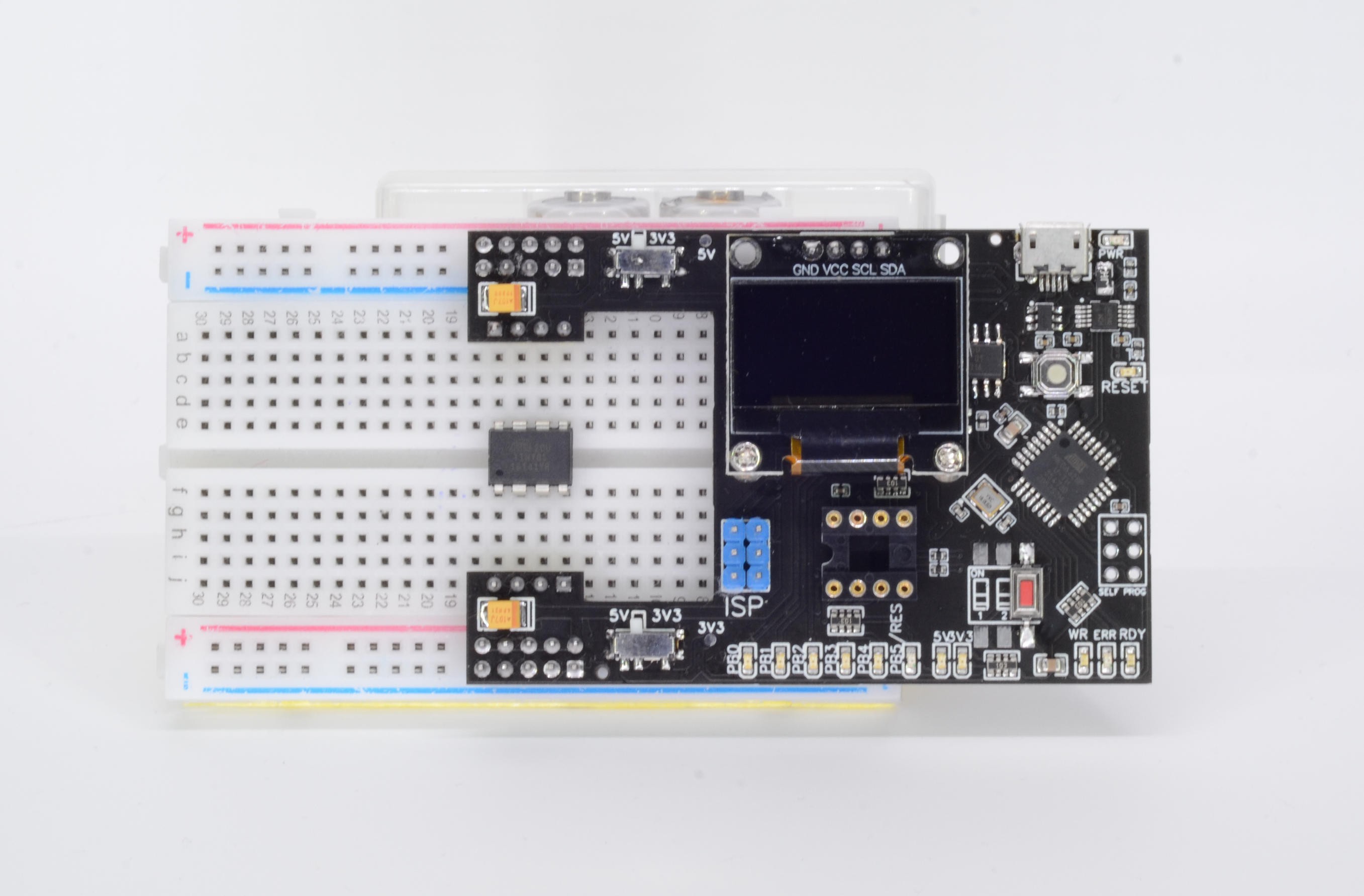
- Supports flashing ATtiny13/25/45/85 using onboard socket or on breadboard
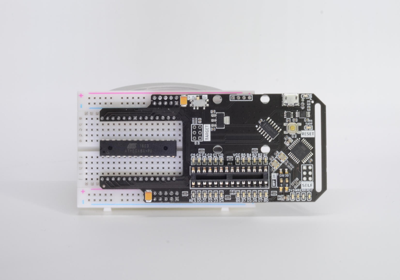
- Supports ATtiny, ATmega MCUs using ISP header
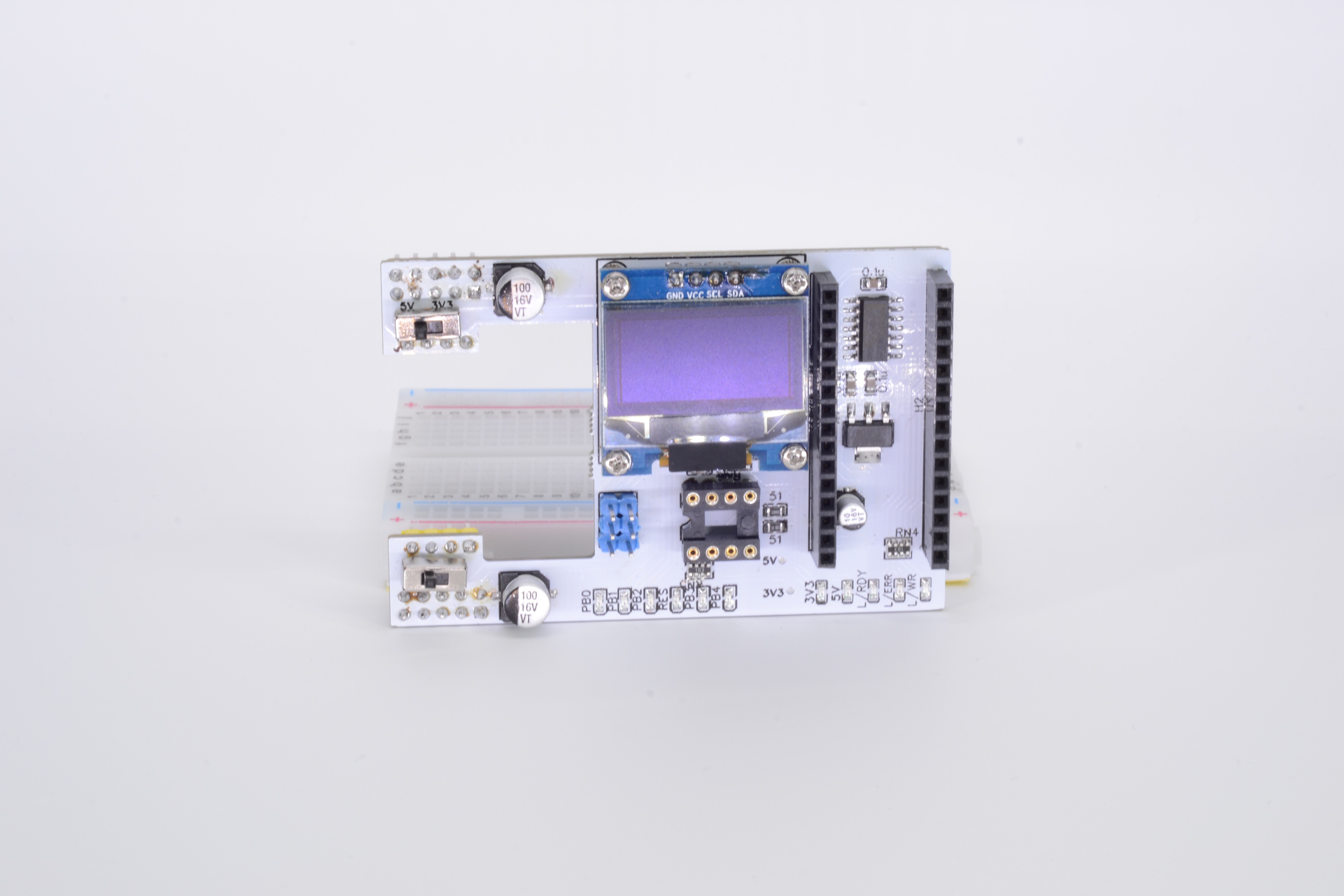
- 2 configurable power rails, either 3.3V or 5V
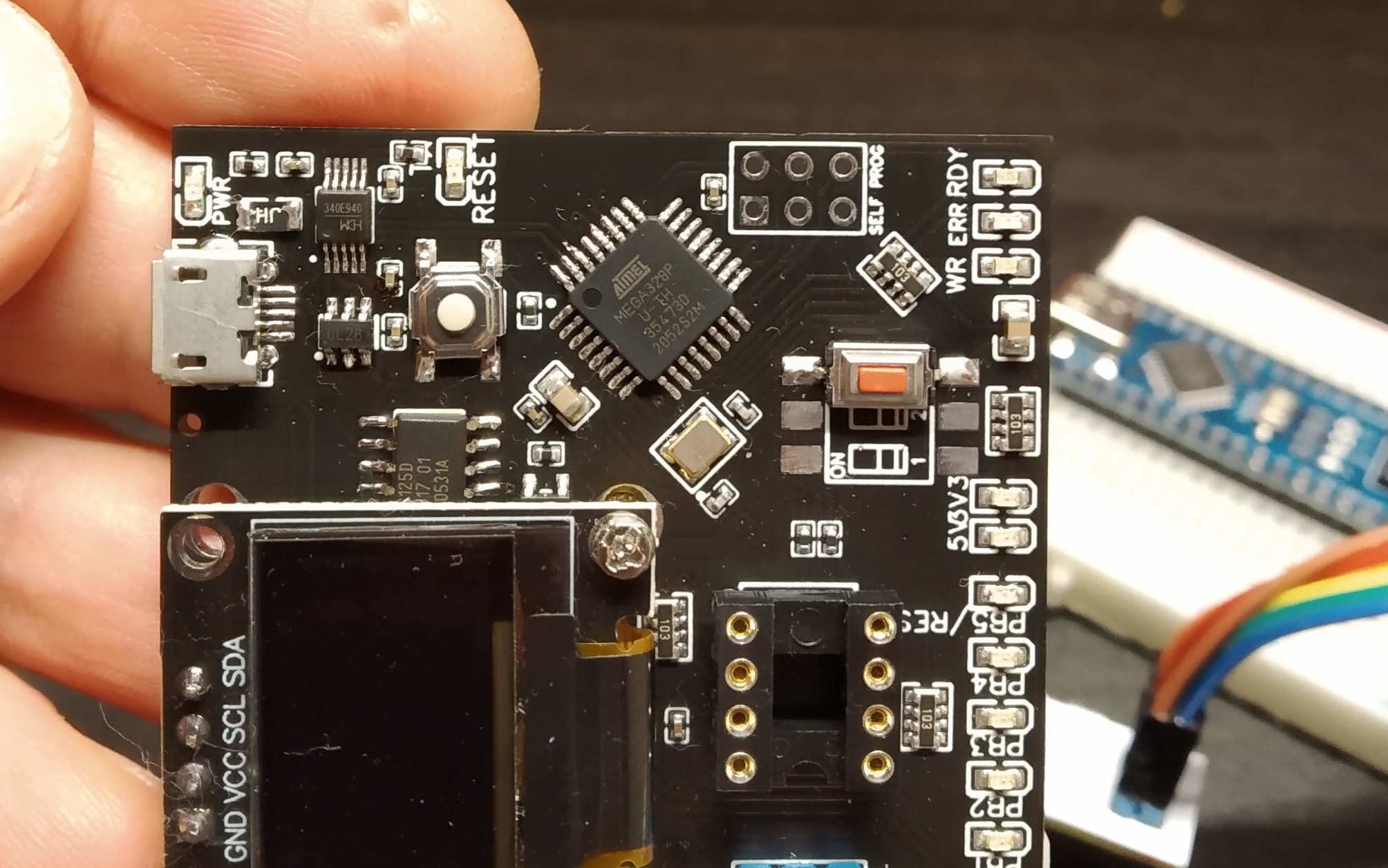
- 6 GPIO "weak" LEDs
- 3 flash status LEDs
- Onboard OLED screen connected to target MCU as live terminal
- Streams serial data to host PC, as if you'd be connected directly
- Buffer IC between target and host MCUs, only connects them together while flashing
- Open source, open hardware
Credits
- Based on ArduinoISP code by Randall Bohn, with few features added
- Thanks Microchip for superb value for money MCUs


 Sam Ettinger
 Ken Yap
Nice thing. Add more pinouts. atmega8 pinout needed.