 Sander van de Bor
This free form circuit sculpture consist of a super capacitor, ATtiny412 micro controller, two LED's , a push button and some decoration like resistors.
The ATtiny412 can be programmed, by using an adapter that connects the USB beak to a programmer. The beak is also used to charge the super capacitor from any USB power source. Programming can be done in Arduino.
There is a push button underneath the beak that is connected to the ATtiny412 as well. This push button can be used to change the pattern the LED is flashing or can put the duck in sleep mode.
See following video for the entire build:
Demo showing the different light patterns. Short click of the push button will change the pattern while holding the button for a longer time will put the Duck in sleep mode:
Code used:
/*
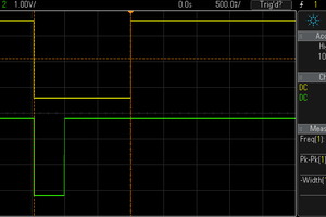
TCB0 (20MHz / (32 * 2 * (255+1)) = 1220.703Hz = 0.8192ms per cycle:
0 0.8192|0
+--+ +--+
| | | |
+ +-------------------+ +-------------------
0 x28 xFF/0
TCD: (20MHz / (4 * (4092+1)) = 1221.598Hz = 0.8186ms per cycle:
*/
#include <stdio.h>
#include <avr/sleep.h>
#include <avr/eeprom.h>
#include <avr/interrupt.h>
#define USERROW_OFFSET (0x1400)
volatile uint8_t pattern;
typedef enum st_pushbutton_state {
PATTERN,
SLEEP,
WAKEUP,
RESET,
} pushbutton_state_t;
volatile pushbutton_state_t pb_state = PATTERN;
void update_TCD_pattern(uint8_t p)
{
TCD0.CMPBCLR = 4090 + (p & 0x03);
TCD0.CMPBSET = 3069 + 310 * ((p >> 2) & 0x03);
TCD0.CMPACLR = 2090 + 610 * ((p >> 3 & 0x01) ^ (p >> 2 & 0x01));
TCD0.CMPASET = TCD0.CMPACLR - ((TCD0.CMPBCLR - TCD0.CMPBSET) / (5*((p >> 3 & 0x01) ^ (p >> 2 & 0x01))+1));
}
void push_button_action(void)
{
switch(pb_state)
{
case PATTERN: // Fast pattern
if(pattern++ > 0x15) pattern = 0x00;
while (NVMCTRL.STATUS & NVMCTRL_EEBUSY_bm);
eeprom_write_byte((uint8_t*)(&USERROW.USERROW0 - USERROW_OFFSET), pattern);
while (NVMCTRL.STATUS & NVMCTRL_EEBUSY_bm);
case RESET:
_PROTECTED_WRITE(RSTCTRL.SWRR, RSTCTRL_SWRE_bm);
break;
case WAKEUP:
CCL.CTRLA = 1 << CCL_ENABLE_bp; /* Enable: Enabled */
RTC.CTRLA = 0 << RTC_RTCEN_bp;
pb_state = RESET;
break;
case SLEEP:
CCL.CTRLA = 0 << CCL_ENABLE_bp; /* Enable: disabled */
PORTA_DIRCLR = PIN7_bm;
set_sleep_mode(SLEEP_MODE_PWR_DOWN); /* Set sleep mode to IDLE mode */
}
}
void TCB0_init(void)
{
TCB0.CTRLA = TCB_CLKSEL_CLKDIV2_gc /* CLK_PER/2 (From Prescaler) */
| 1 << TCB_ENABLE_bp; /* Enable: enabled */
TCB0.CTRLB = 1 << TCB_CCMPEN_bp /* Pin Output Enable: enabled */
| TCB_CNTMODE_PWM8_gc; /* 8-bit PWM */
TCB0.CCMP = 0x28FF; /* 8-bit mode. Period = 255 (0xff), cmp = 40 (0x28) */
}
void TCD0_init(void)
{
TCD0.CTRLB = 0x00; /* Disable Dual slope mode */
update_TCD_pattern(pattern);
while ((TCD0.STATUS & TCD_ENRDY_bm) == 0); /* Wait for Enable Ready to be high */
TCD0.CTRLA = 1 << TCD_ENABLE_bp /* Enable: enabled */
| TCD_CNTPRES_DIV4_gc; /* Sync clock divided by 4 */
}
void RTC_init(void)
{
RTC.CLKSEL = RTC_CLKSEL_INT32K_gc; // 32.768kHz Internal Crystal Oscillator (INT32K)
while (RTC.STATUS > 0); // Wait for all register to be synchronized
RTC.PER = 0x7D0; // Max for overflow (2 sec)
RTC.CMP = 0x32; // Compare at 50ms
RTC.CNT = 0x0;
RTC.INTCTRL |= RTC_OVF_bm; // Enable overflow Interrupt which will trigger ISR
RTC.INTCTRL |= RTC_CMP_bm; // Enable compare Interrupt which will trigger ISR
RTC.CTRLA = RTC_PRESCALER_DIV32_gc // 32768 / 32 = 1024 (Hz) ~ 1 ms
| RTC_RTCEN_bm // Enable: enabled
| RTC_RUNSTDBY_bm; // Run In Standby: enabled
}
void CCL_init(void)
{
CCL.LUT1CTRLB = CCL_INSEL0_TCD0_gc /* TCD0 WOA input source */
| CCL_INSEL1_TCD0_gc /* TCD0 WOB input source */;
CCL.LUT1CTRLC = CCL_INSEL2_TCB0_gc /* TCB0 WO input source */;
CCL.TRUTH1 = 0x60; /* Truth 0: 0x9F */
CCL.LUT1CTRLA = 1 << CCL_ENABLE_bp /* LUT Enable: enabled */
| 1 << CCL_OUTEN_bp; /* Output Enable: enabled */
CCL.CTRLA = 1 << CCL_ENABLE_bp /* Enable: enabled */
| 0 << CCL_RUNSTDBY_bp; /* Run in Standby: disabled */
}
void PORT_init(void)
{
for (uint8_t pin...
Read more »


 Frank Buss
 Alex
Alex
 The Curious Lorenz
 danjovic
I"ll second that cute :-)