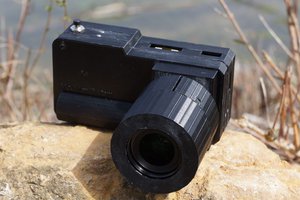
Close
0%
0%

LOMOPI - Digital TLR Camera

The RPi-Powered Twin-Lens Reflex Street Photography Camera.

Similar projects worth following
**Project Re-Activated!**

A Raspberry Pi-based digital Twin Lens Reflex camera, built inside the shell of a soviet LOMO Lubitel 166! No LCD, no tapping menus or pixel peeking, no fancy settings...hell, basically no settings at all. I want to turn this thing on - press a button - and be done.

✓ Now with HQ Raspberry Camera
✓ Keeps original viewing lens and focus screen
✓ Using ChatGPT4 to write the code

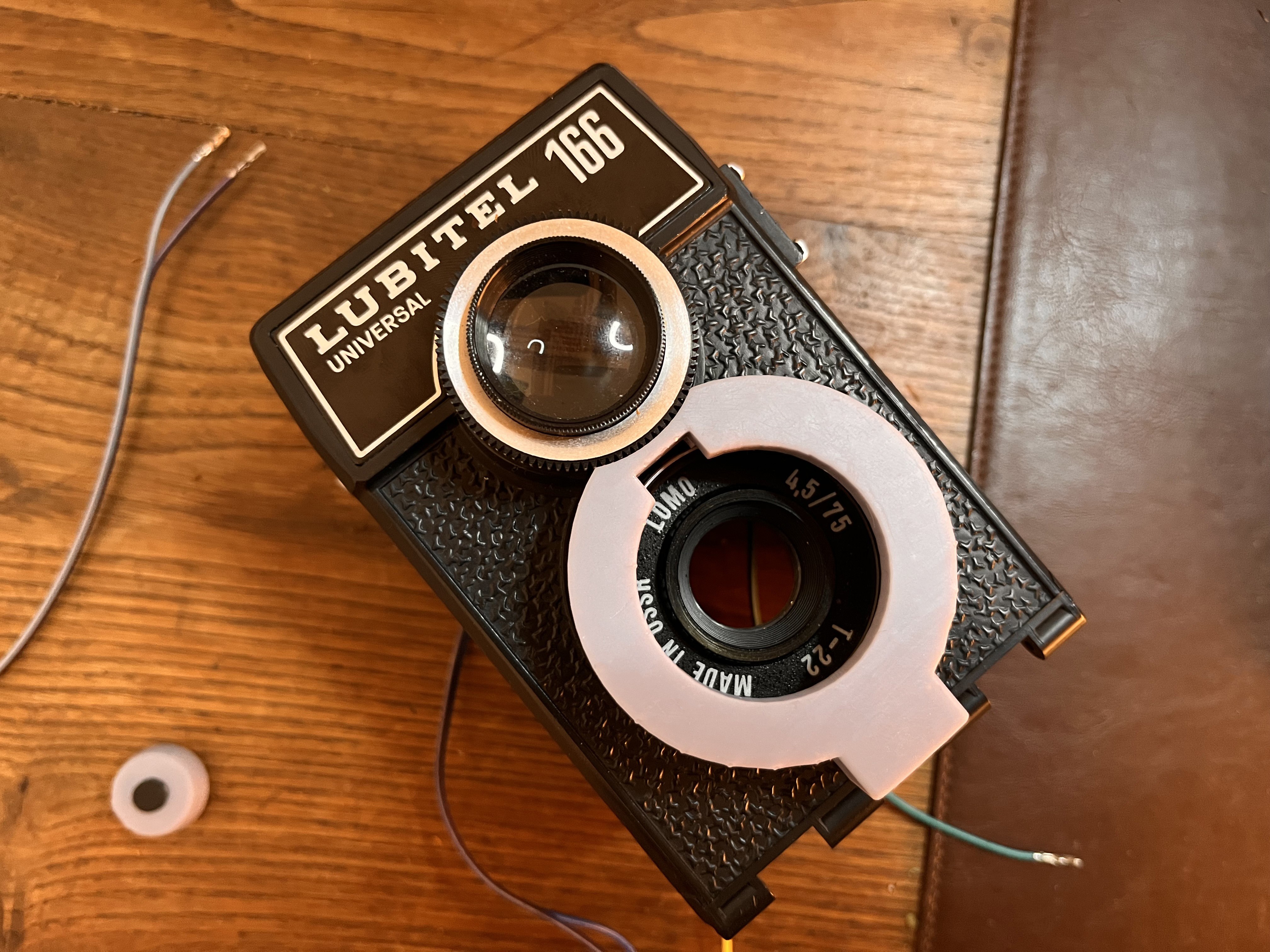
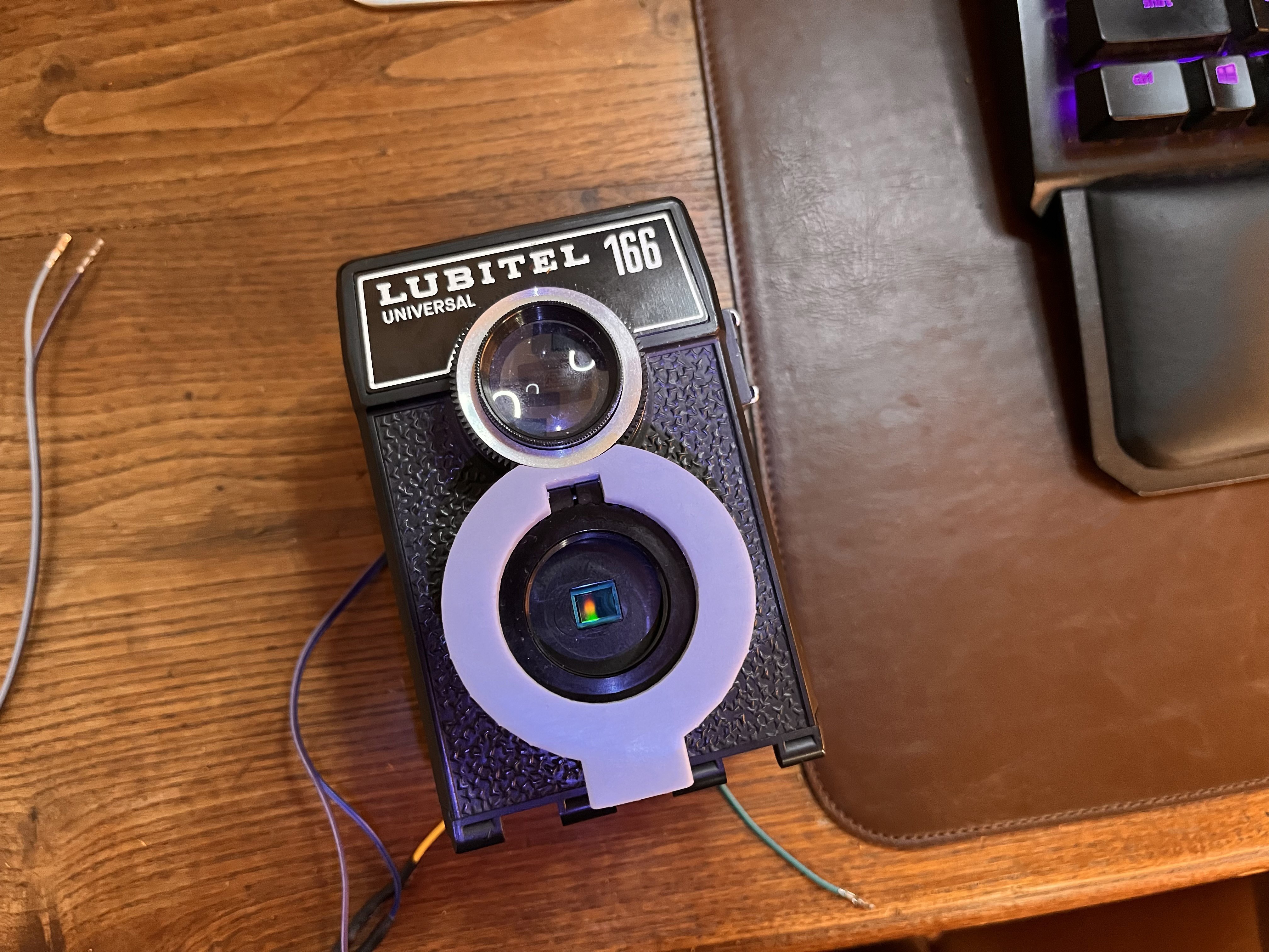
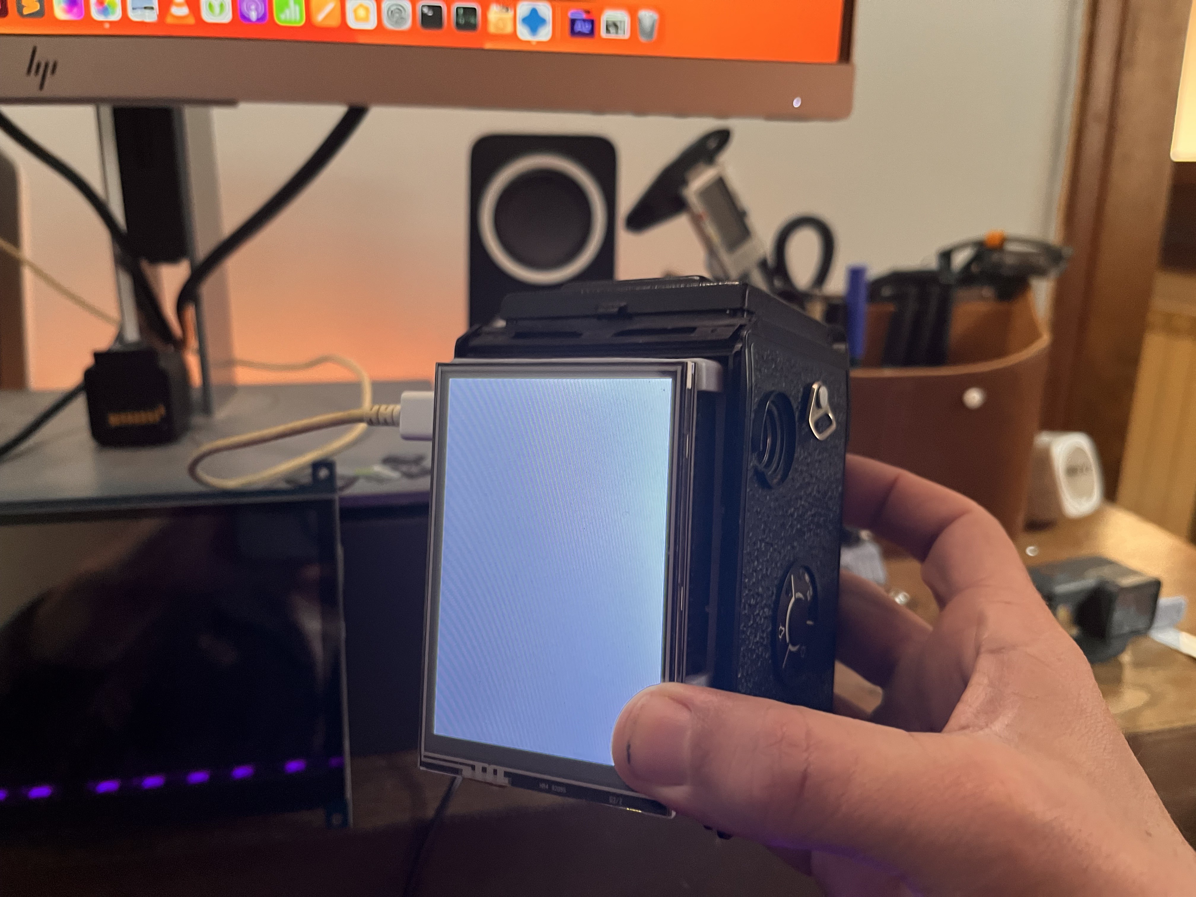
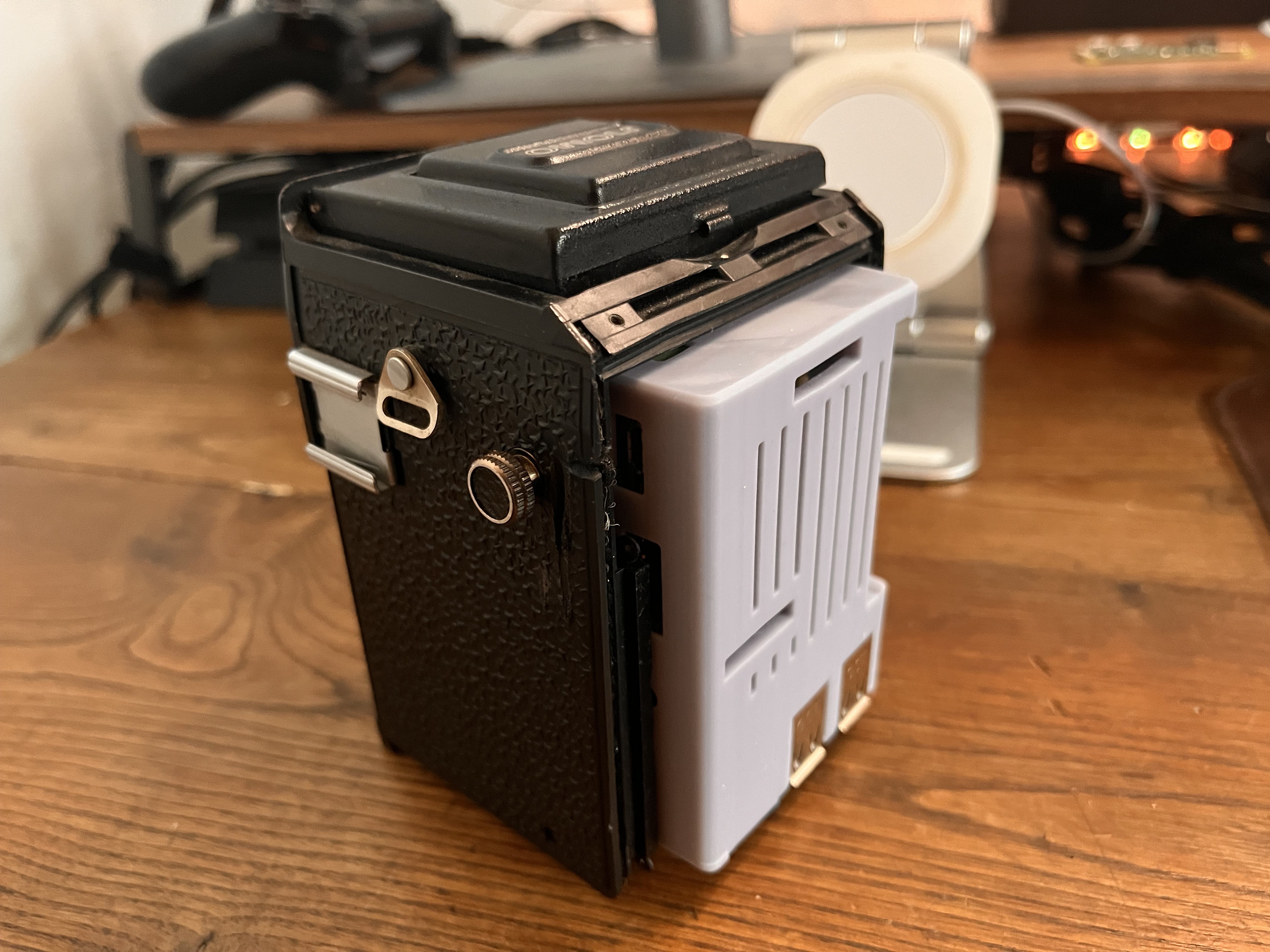
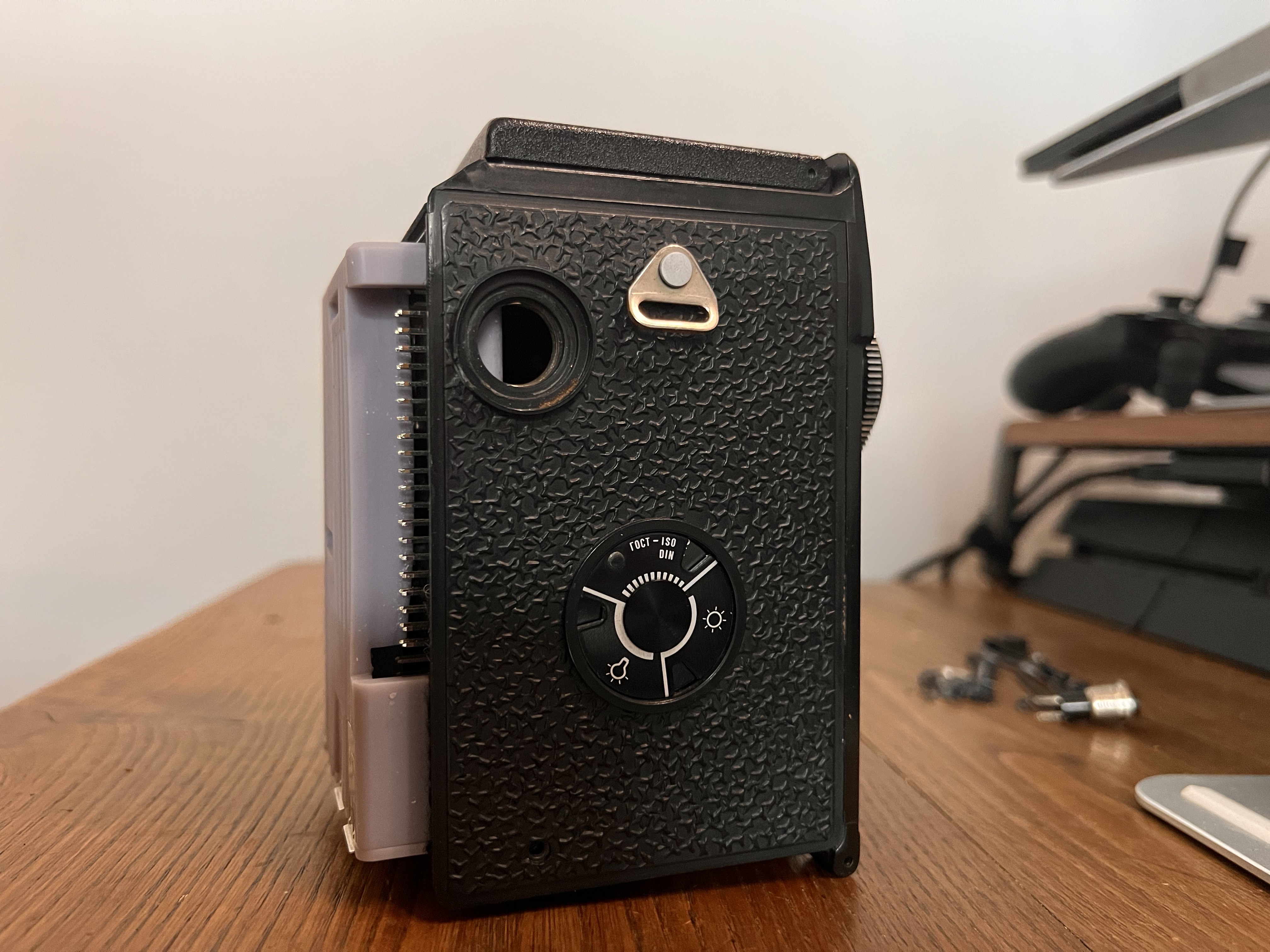
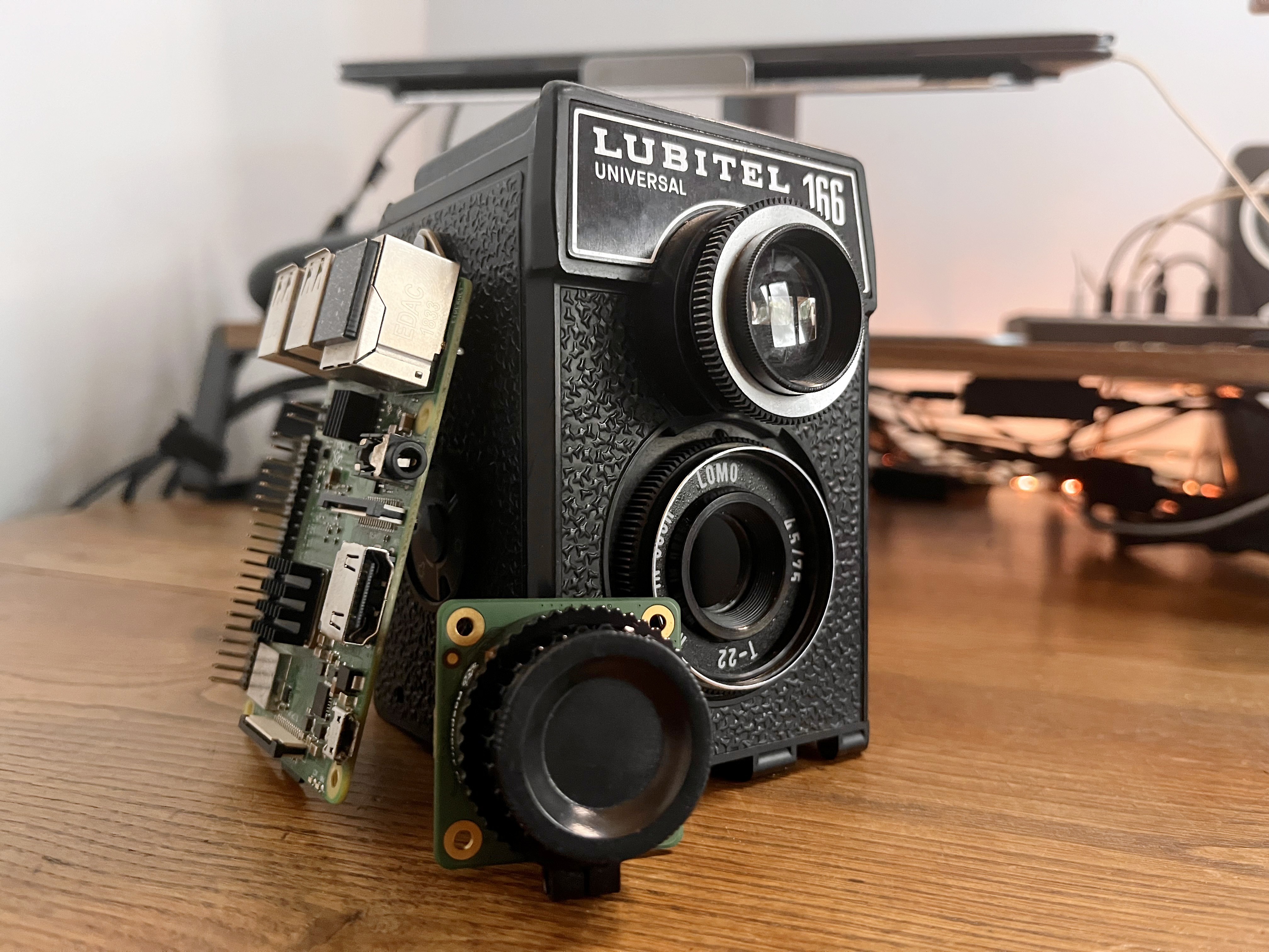
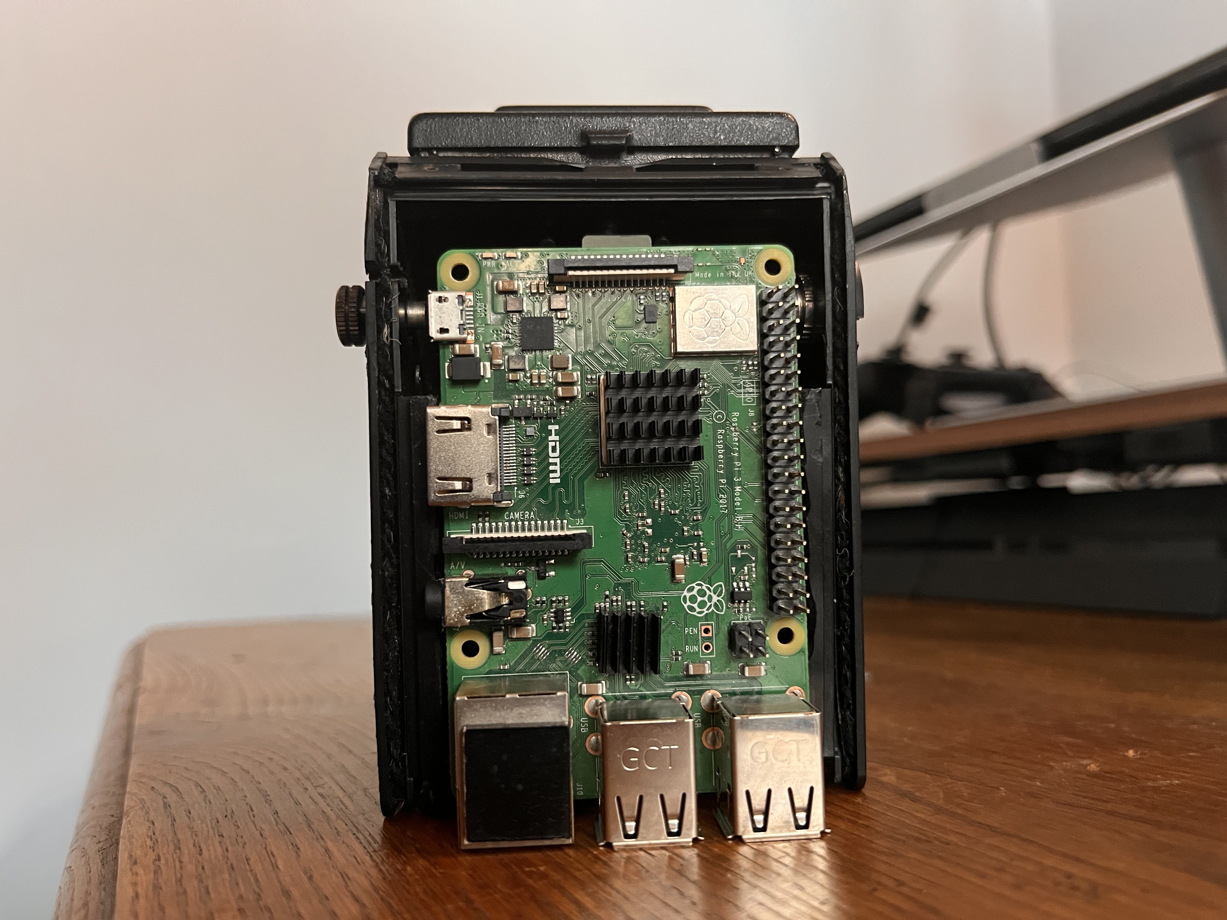
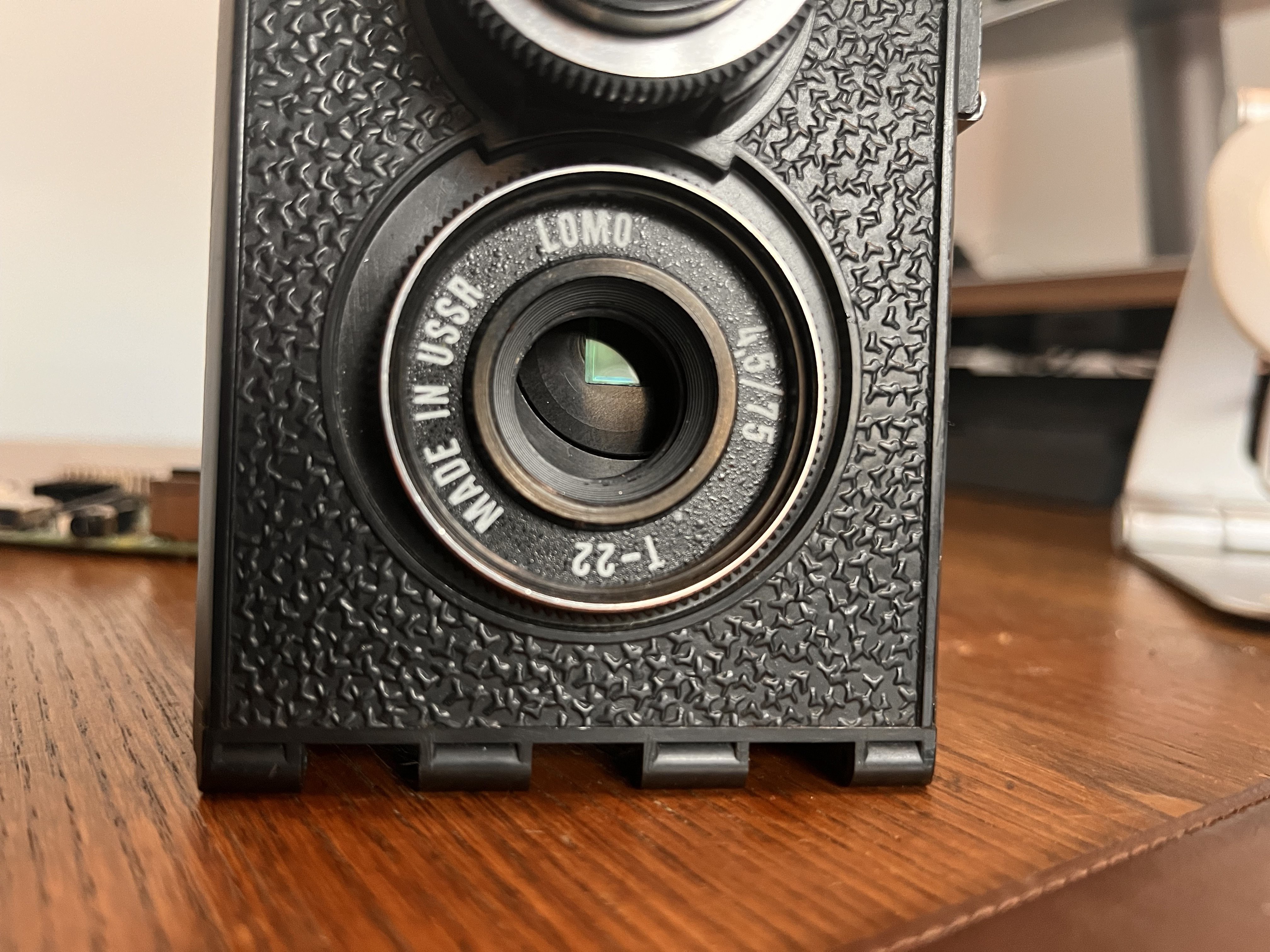
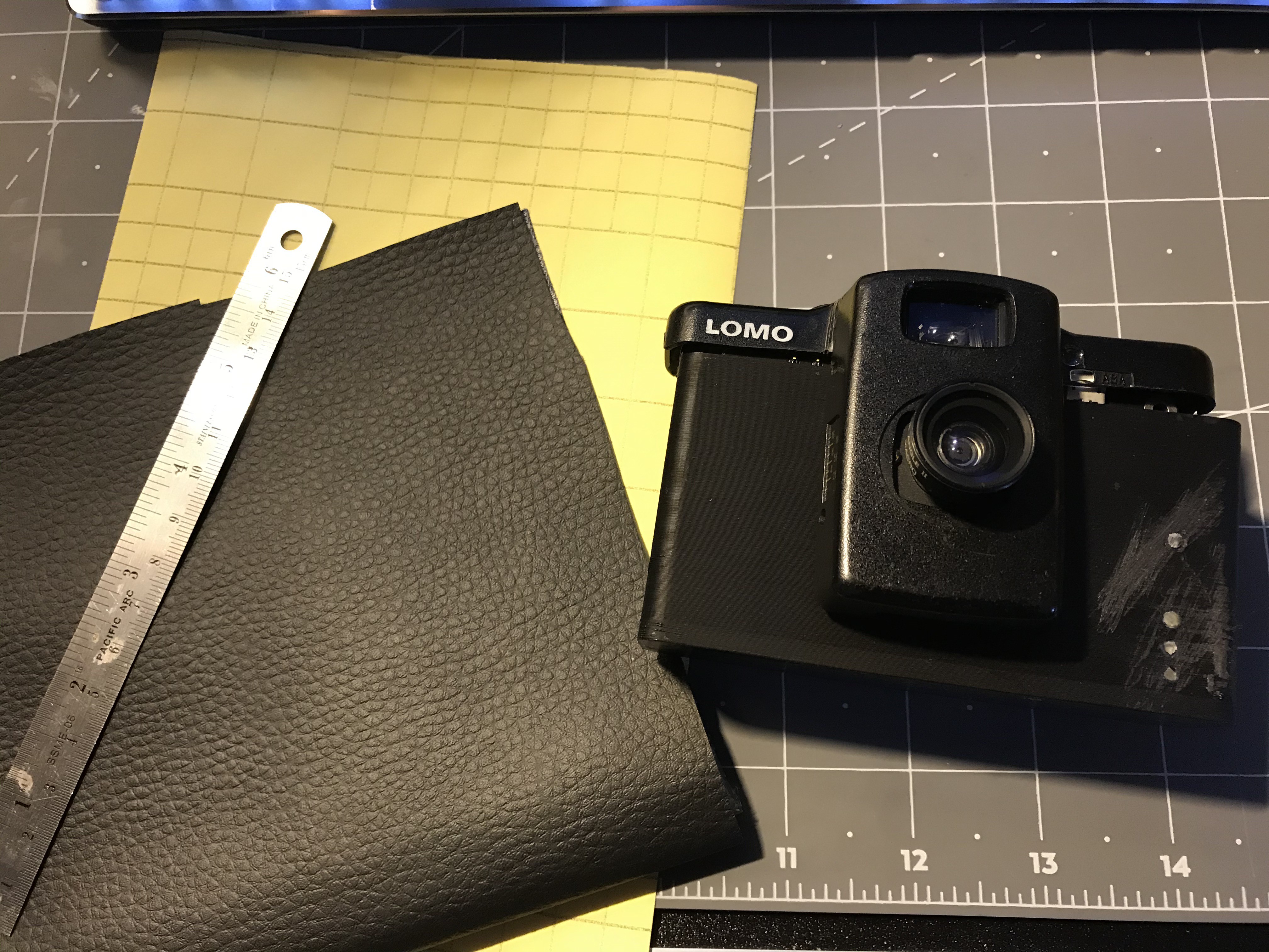
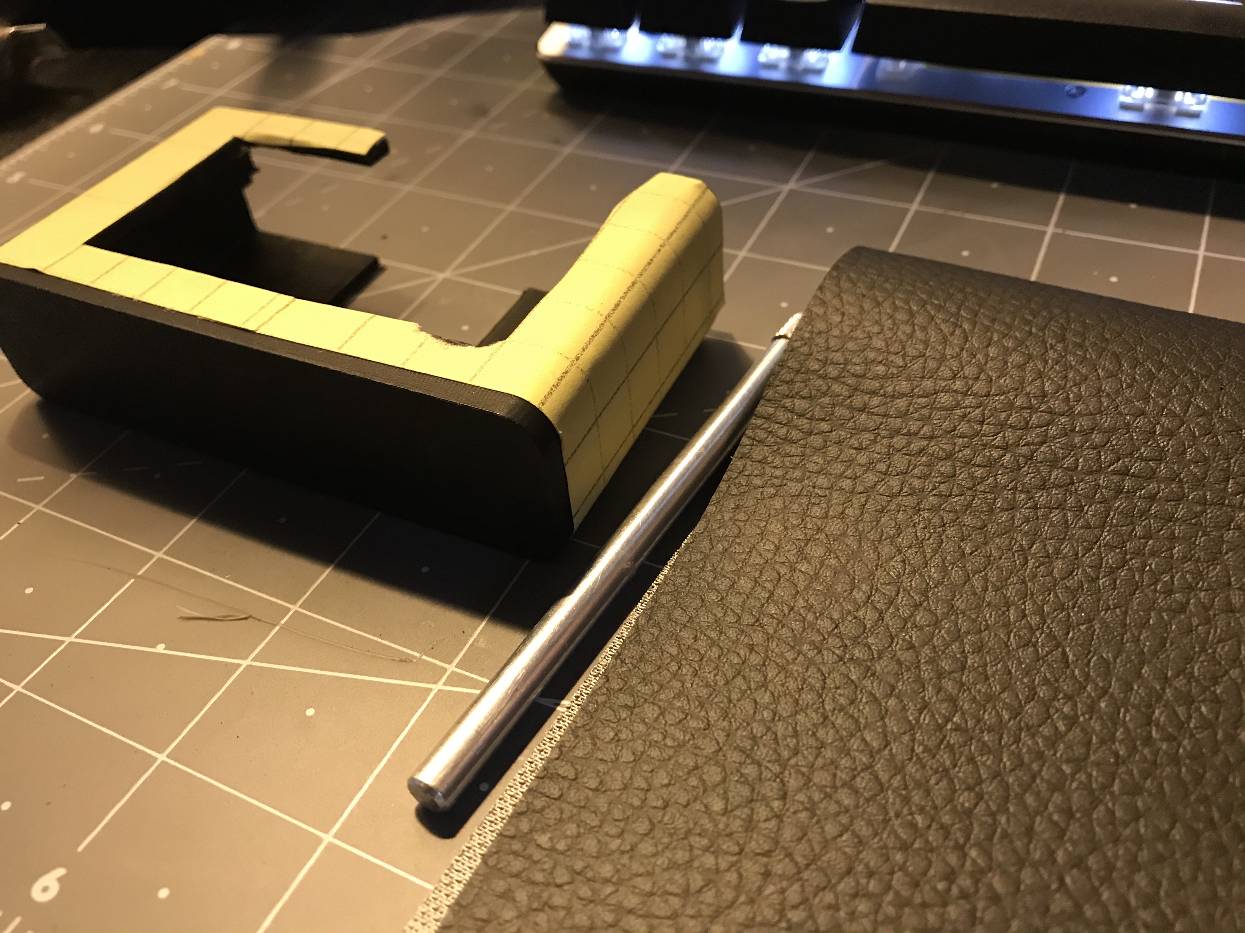
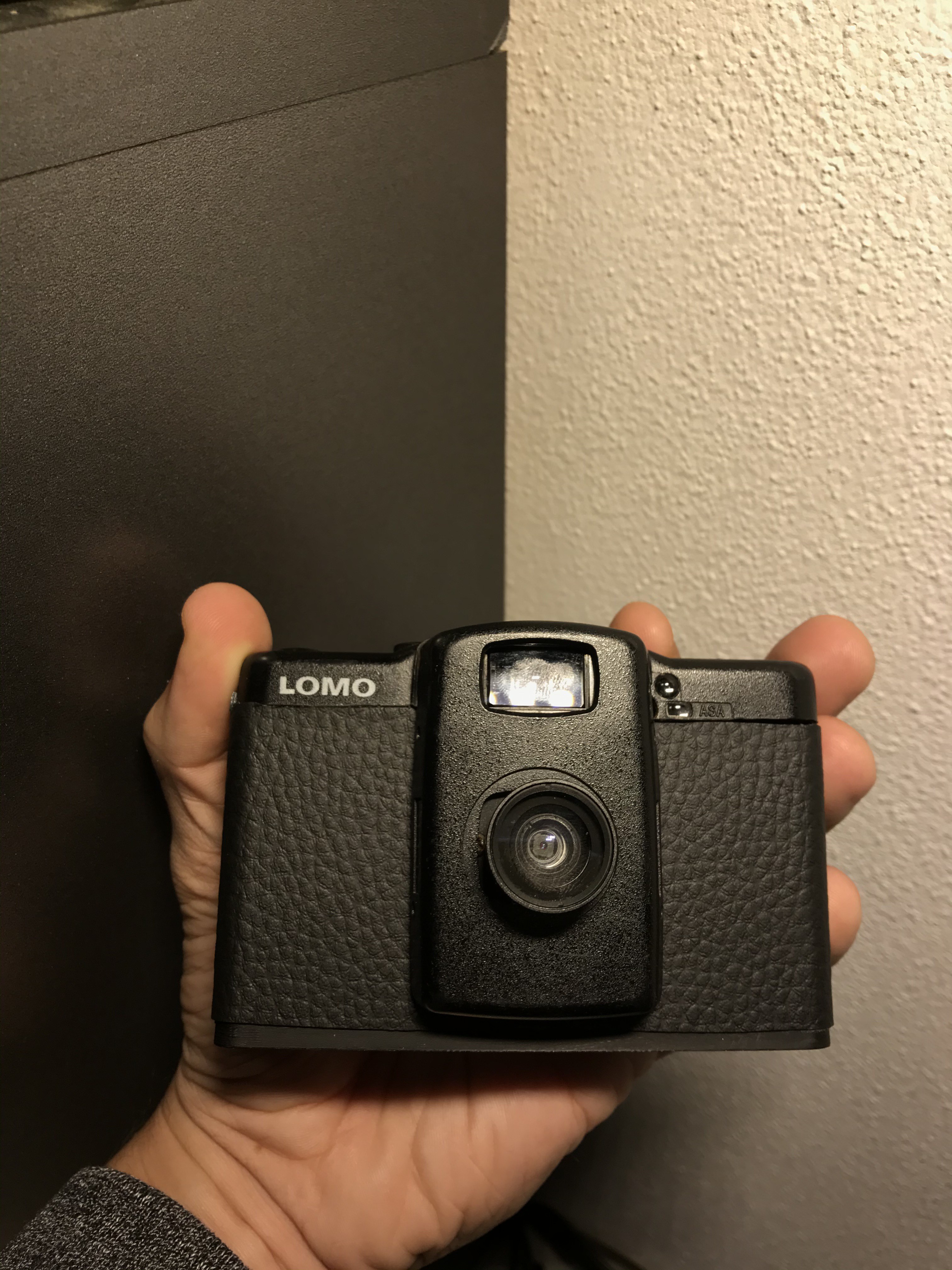
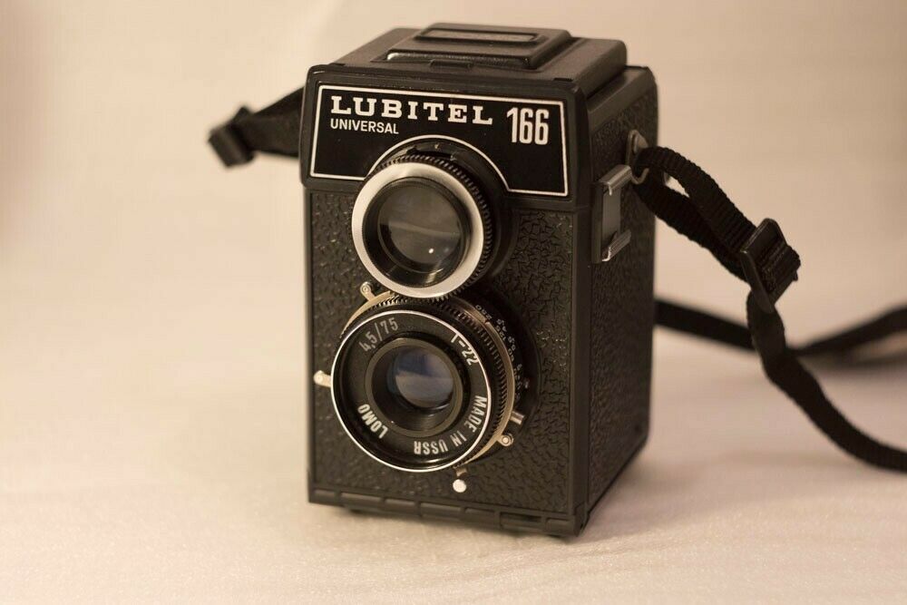
I shot my first roll on film in the year 2000, and have been in love with it ever since. I still shoot film regularly along with digital, but other than my Fujifilm X series have never really had a FUN digital camera to play with. I miss shooting from the hip with a straight forward camera. One without all the bells and whistles that I find often distract from simply making art, and not some overpriced hipster sh*t sold at UO that automatically syncs with your Instagram to make sure those artificial little pumps of your daily social dopamine don't cease. Just press a button, take a picture - MAYBE twist a dial but not more. What better enclosure than the no-nonsense, almost brutalist LOMO cameras for such a project? 


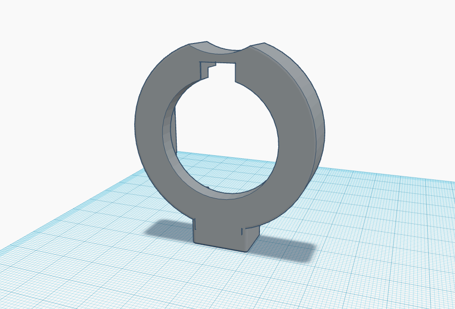
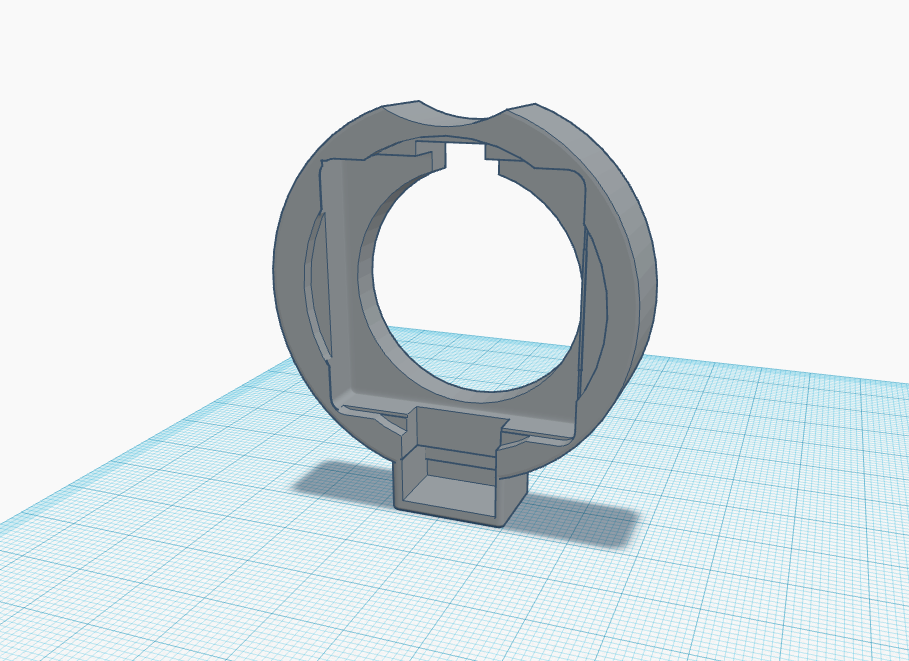
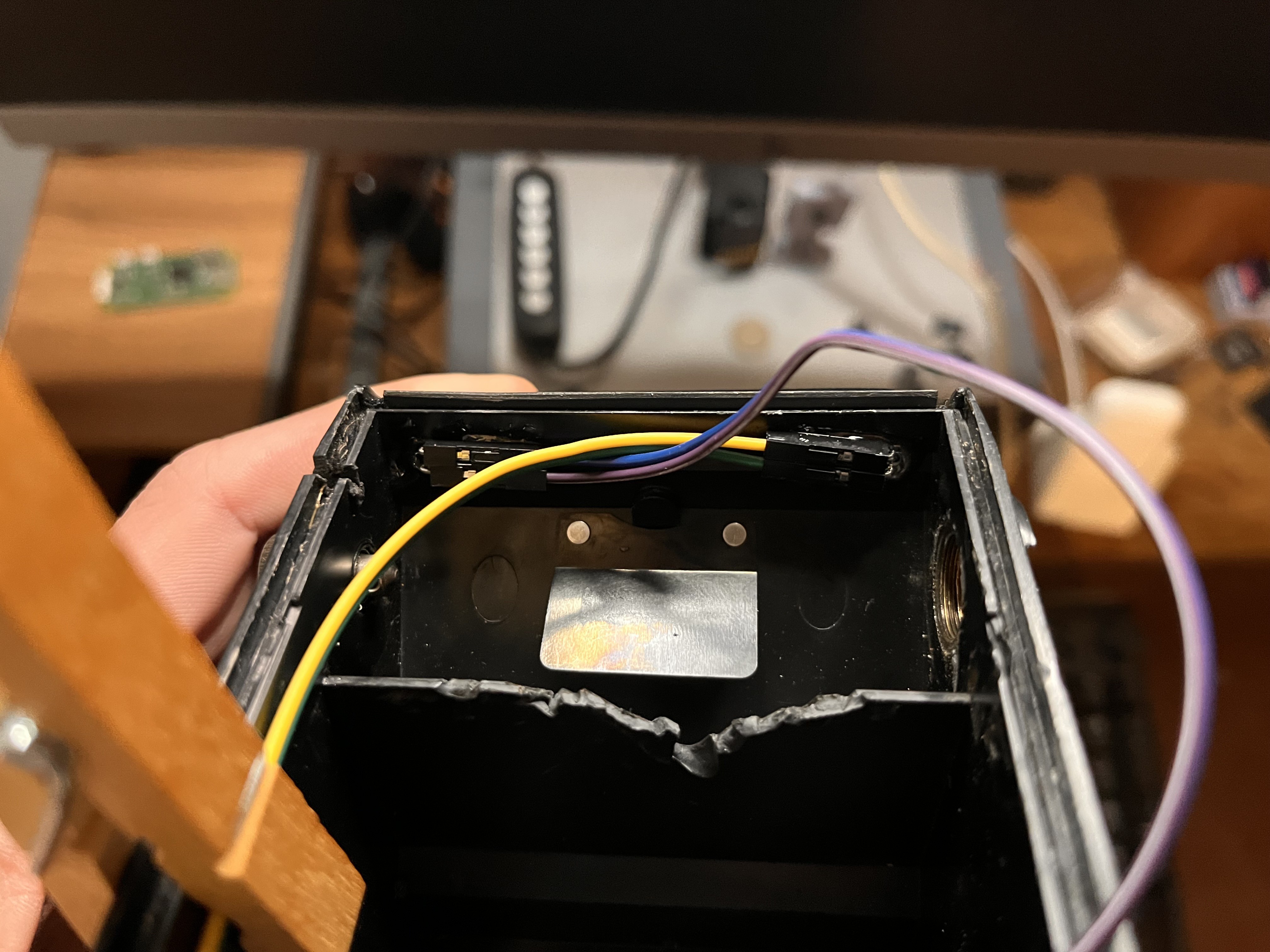
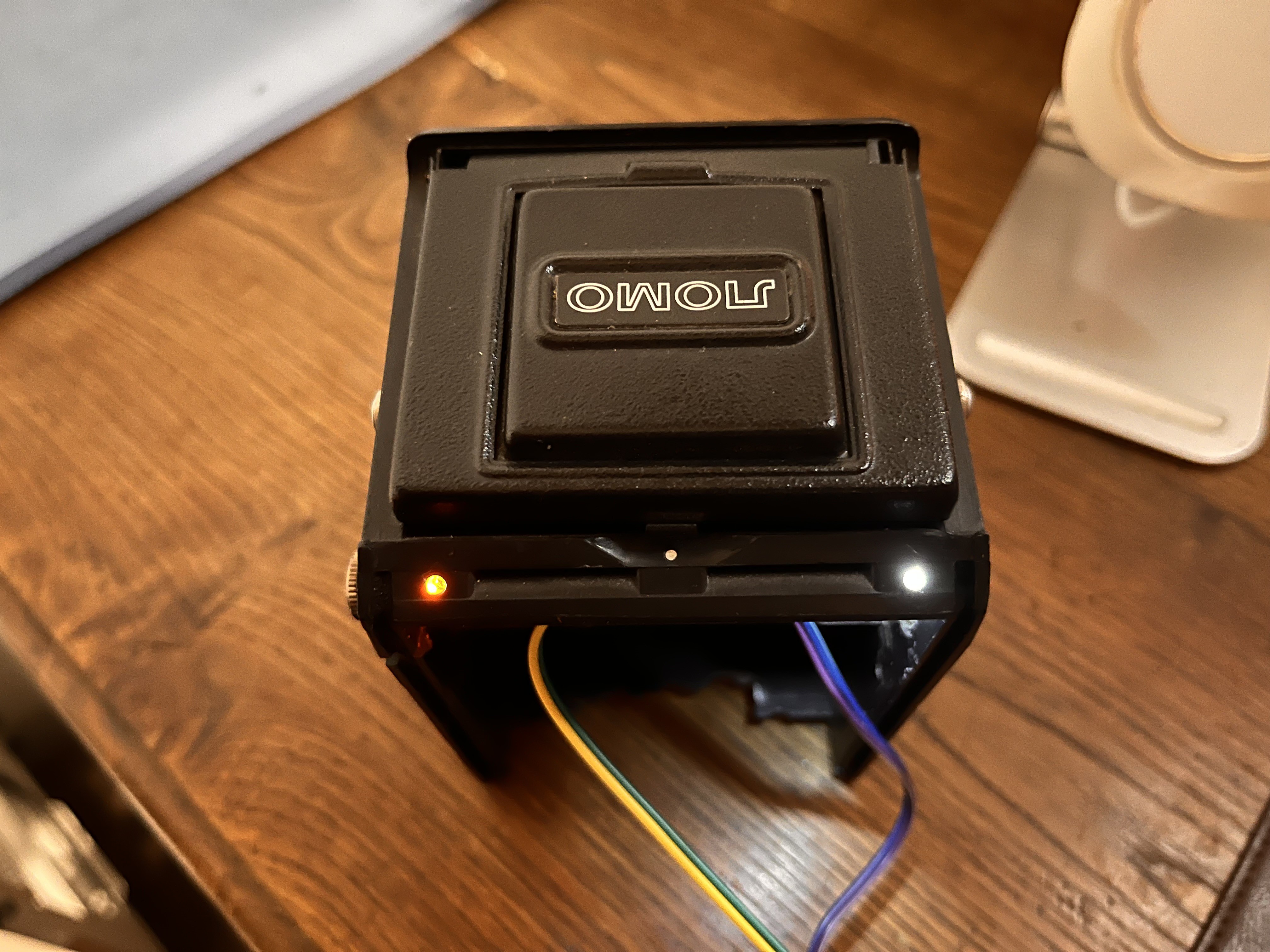
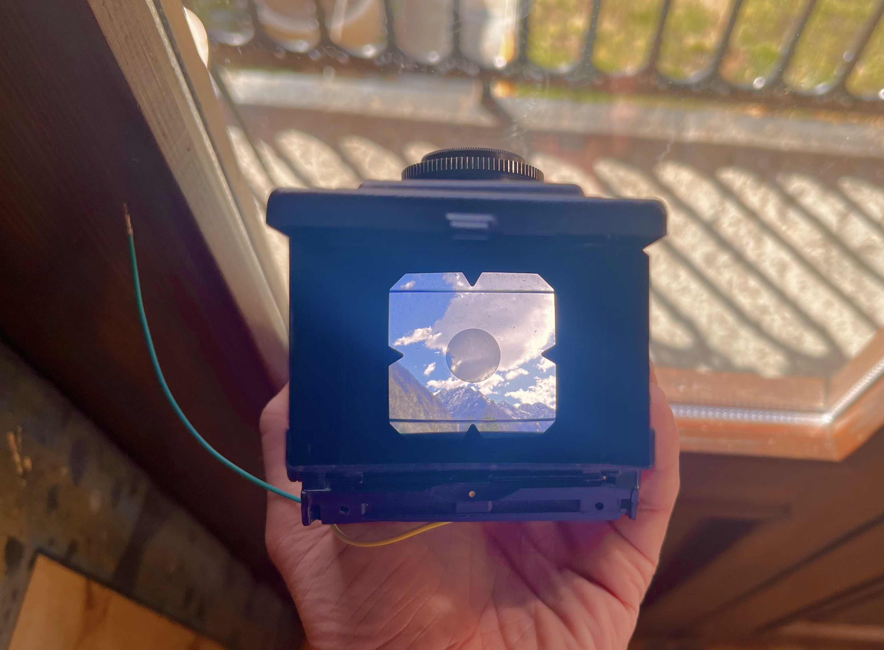
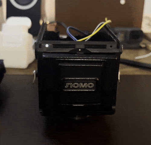
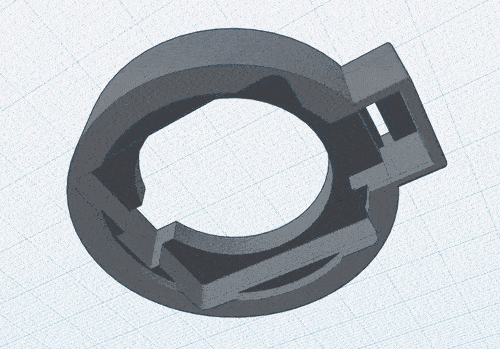
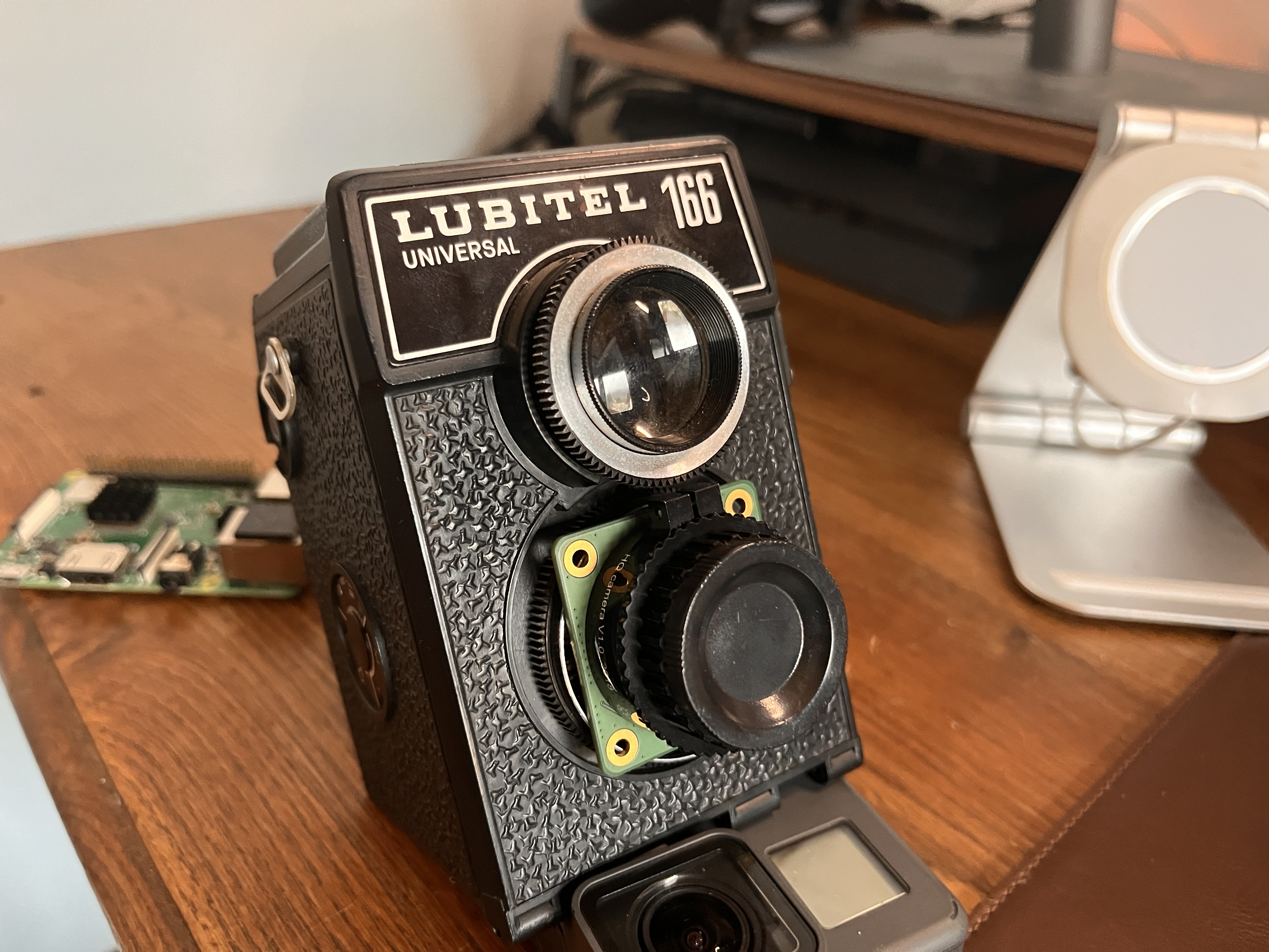
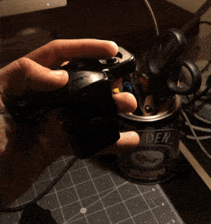
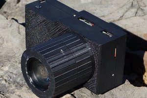
So with almost zero 3D modelling experience, only one successful RPi project under my belt, and a collection of skills learnt only from reading books and raw experience...I set out to make the LOMOPI. 

LomoPi-Slimfit.stl

The first version of the 3D printed body to put an Raspberry Pi inside a Lomo LC-A. It's not a perfect fit, and needs to be updated - but should give you a decent start if you want to make your own. Kept here for posterity.

Standard Tesselated Geometry - 20.69 kB - 11/10/2020 at 16:38

Download

  • 1 × Raspberry Pi (3 or 4)
  • 1 × Raspberry Pi HQ Camera Module (Normal camera can also be used, but I think HQ is worth it.)
  • 1 × Broken LOMO Lubitel 166 But should work with most TLRs
  • 1 × LiPo Battery/Powerpack or 18650 holder with charge port
  • 1 × 3D printed case

View all 7 components

  • PART 9: Some progress on the backer & ChatGPT4 code

    Gradivis04/07/2023 at 15:10 0 comments

    My black printing resin has been delayed by the Italian Post (story of my life). In the mean time, I'm still working on the back panel and battery holder design.

    This is the general idea so far - it definitely needs some more work, and Tinkercad is just too limiting for really polishing off a design (edges/surfaces). If anyone can recommend a better free CAD software similar to how Google Sketchup used to be, I would be eternally grateful.

    The back plate (if I measured correctly) should be almost there though, and I'll be importing an SVG I found that is close to the pattern of the original LOMO plastic for some texture, although it might be too complex as the import seems to be timing out.

    I have a cut out - which I hope it big enough - for the micro USB that will run from the RPi to the battery/power management chip, once I've figured out how I want to incorporate that next to the battery. The good news is that I should be able to get a 2000mah battery in there at least without it being too cramped.

    The bottom is primitive for now - there's a lot of harmonization that needs to be done and as I mentioned before, edge work that is a PITA in Tinkercad in my experience. Perhaps I'm using it wrongly?


    Using ChatGPT4 to write the code

    I decided I wanted to revisit the code and simplify things. After refining my prompt (and borrowing my brother's ChatGPT4 account) I'm actually optimistic this might work! I'm saving it here so I can easily access it from my Rpi directly - I'll report back on whether it works or not!

    I've gone for a simple set-up and single button - I didn't want to have to drill unnecessarily into the LOMO body. <2 second press will take a raw image, >2 seconds will take a video until released - LED will either be solid until image has finished saving, or blink during video until the same.

    import time
    import RPi.GPIO as GPIO
    from datetime import datetime
    from libcamera import CameraManager
    
    # Set up GPIO pins
    GPIO.setmode(GPIO.BCM)
    GPIO.setup(8, GPIO.IN, pull_up_down=GPIO.PUD_UP)
    GPIO.setup(14, GPIO.OUT)
    
    # Initialize camera
    cm = CameraManager()
    camera = cm.get_device("raspberrypi").get_control()
    
    while True:
        # Wait for button press
        GPIO.wait_for_edge(8, GPIO.FALLING)
    
        # Get start time for timestamp
        start_time = time.time()
    
        # Check button hold time for photo or video capture
        while GPIO.input(8) == GPIO.LOW:
            # Button held for less than 2 seconds, take photo
            if time.time() - start_time < 2:
                # Turn on LED
                GPIO.output(14, GPIO.HIGH)
    
                # Capture photo
                timestamp = datetime.now().strftime('%Y-%m-%d_%H-%M-%S')
                filename = f'Lomopi_TLR_{timestamp}.raw'
                with camera.capture(filename, format='raw') as buffer:
                    buffer.save(f'/media/images/{filename}')
    
                # Turn off LED
                GPIO.output(14, GPIO.LOW)
    
                print(f'Photo {filename} saved successfully')
    
            # Button held for more than 2 seconds, start video recording
            else:
                # Turn on LED flashing
                while GPIO.input(8) == GPIO.LOW:
                    GPIO.output(14, GPIO.HIGH)
                    time.sleep(0.5)
                    GPIO.output(14, GPIO.LOW)
                    time.sleep(0.25)
    
                # Capture video
                timestamp = datetime.now().strftime('%Y-%m-%d_%H-%M-%S')
                filename = f'Lomopi_TLR_{timestamp}.mp4'
                with camera.create(filename, format='mp4') as recording:
                    recording.start()
                    while GPIO.input(8) == GPIO.LOW:
                        time.sleep(0.1)
                    recording.stop()
    
                print(f'Video {filename} saved successfully')
    
    # Clean up GPIO pins
    GPIO.cleanup()
    

    Here's the prompt I used:

    Write me python code for the Raspberry pi and Rpi camera, using libcamera and GPIO with the following parameters:

    LED on GPIO 14, Button on GPIO 8

    When the button is pressed for less than two seconds, a 4056x3040 pixel image in RAW filetype should be saved to root/media/images. The file name will be "Lomopi_TLR_{date}-{time}" where {date} and {time} are retrieved. During this time, the LED should turn on until the image has finished saving, and a message should be printed that the image was saved successfully.

    When the button is pressed for more than two seconds, a 1920x1080...
    Read more »

  • PART 8: Button Cover and Lens Mount

    Gradivis04/02/2023 at 11:41 0 comments

    Since I no longer have sketchup, I threw a button cover together in Tinkercad relatively quickly after measuring the button with calipers. This is my first print from Tinkercad, and while it's a straight forward program I'm still on the switching learning curve, and there are some tools (such as the line tool) that I really miss. That said, a button cover is simple enough as you can see:


    It was a snug fit (I didn't add much in terms of tolerances) but with the help of some pliers I got the button in! Diameter was spot-on - it fits perfectly in the circle that the winding knob used to sit it. Here's a preview:

    A little bit more complex, was the lens mounting system. The HQ Rpi camera comes on a square circuit board, but I wanted to keep the TLR aesthetic by making the lens mount round.

    I sketched everything out on paper, and then started building the basic shapes in Tinkercad for a rapid prototype. To cut down on the work, I found an STL of the HQ camera and basically subtracted it from the mount I had built.

    What I forgot to do was enlarge the camera model slightly, because after printing I found that it was just too snug of a fit to get the camera module in. I'm reprinting when my black resin comes in anyway, but the good news is that the mount itself will fit the TLR really nicely!


    I feel like the front needs some embellishments or texturing in certain areas, maybe emboss the original text on the front and fill with white? Decisions, decisions.

    Here's what it will end up looking like. Look at that sexy little sensor back there...

    I'm going to wait until my black resin comes in before adjusting and re-printing. The camera cable could use a little bit more breathing room, as well as a few minor other adjustments I hope I don't forget about. I also need to think about an impermanent solution to attaching the lens mount to the front. I have some ideas. The button will just get epoxyed - I can remove and re-do if it ever breaks.

    In the mean time, I'm going to start working on the design for the battery holder and backer that should bring everything together!

  • PART 7: LEDs & ChatGPT Code

    Gradivis04/01/2023 at 08:51 0 comments

    The LEDs were one of the easiest parts so far, other than deciding placement. I wanted two LEDs - one for camera power, the other for providing information on camera status.

    I decided to re-use two small holes that were already in the back of the camera and facing upwards. This would allow me to frame a shot and get feedback about when the image or video had finished saving, without needing to move. I had to drill out a bit from the inside for the LEDs to nestle inside, but some epoxy later and they're solidly in place, and out of the way of the RPI:

    As I might have mentioned before, I've kept the viewing lens and screen untouched, so that you can shoot from the waist and frame your shot just like you would with a film TLR! The LOMO screen is nice and bright - here's a demo from my balcony:


    Camera power was easy - once I had inlined a resistor into each negative wire, the anode was directly attached to one of the Pi's 3.3V GPIOs and the cathode to ground. That way it would come on when the RPi was turned on, and as I was going to have a switch between it and the battery power would be totally cut and it would turn off. For the status LED, I hooked the anode up to GPIO16 and the cathode again to ground, right below it.

    I have a pretty demanding job in a tech start up that I love, but it leaves me with very little spare time to learn Python. With the little that I already know, I wrote a tiny script to test the LED - making it a blink a few times as if it were taking and saving a picture. I can at least manage that much ;)


    I'm still deciding whether I want separate photo and video buttons, or whether I do short and long press to determine which the camera should take. In the mean time, I decided to test out ChatGPT (3) for some python code with two buttons and a status LED. It wasn't great - the first attempt was going well until it stopped halfway through. Asking it for the remained of the code missed a big chunk of defining button functions. The second attempt went better from what I can tell but as mentioned Python isn't my forté - I'll have to try it out and see how it goes!

    For those interested, here's what it gave me:

    import datetime
    import os
    import subprocess
    import time
    import RPi.GPIO as GPIO
    from picamera import PiCamera
    
    # initialize GPIO
    GPIO.setmode(GPIO.BCM)
    GPIO.setup(16, GPIO.IN, pull_up_down=GPIO.PUD_UP)  # button for image capture
    GPIO.setup(18, GPIO.IN, pull_up_down=GPIO.PUD_UP)  # button for video recording
    GPIO.setup(12, GPIO.OUT)  # LED
    
    # initialize camera
    camera = PiCamera()
    camera.resolution = (1920, 1080)
    camera.framerate = 30
    camera.rotation = 180
    
    # file path for saving images and videos
    file_path = '/home/pi/Lomopi_TLR'
    
    # function for capturing an image and saving it to the file system
    def capture_image():
        # turn on LED
        GPIO.output(12, GPIO.HIGH)
        
        # capture image
        image_name = 'Lomopi_TLR_{}.jpg'.format(datetime.datetime.now().strftime('%Y-%m-%d_%H-%M-%S'))
        camera.capture(os.path.join(file_path, image_name), quality=100)
        
        # turn off LED
        GPIO.output(12, GPIO.LOW)
    
    # function for recording a video and saving it to the file system
    def record_video(duration):
        # turn on LED
        GPIO.output(12, GPIO.HIGH)
        
        # start recording
        video_name = 'Lomopi_TLR_{}.mp4'.format(datetime.datetime.now().strftime('%Y-%m-%d_%H-%M-%S'))
        camera.start_recording(os.path.join(file_path, video_name), format='h264', quality=25)
        camera.wait_recording(duration)
        camera.stop_recording()
        
        # convert video to mp4 format and delete original file
        mp4_file_name = os.path.splitext(video_name)[0] + '.mp4'
        subprocess.run(['ffmpeg', '-i', os.path.join(file_path, video_name), '-c:v', 'copy', '-c:a', 'copy', os.path.join(file_path, mp4_file_name)], check=True)
        os.remove(os.path.join(file_path, video_name))
        
        # turn off LED
        GPIO.output(12, GPIO.LOW)
    
    # function for starting continuous video recording until button is released
    def start_continuous_video():
        # turn on LED
        GPIO.output(12, GPIO.HIGH)
        
        # start recording...
    Read more »

  • PART 6: Integrating the HQ Camera

    Gradivis03/31/2023 at 16:47 0 comments

    I want to keep the front of the camera as stock as possible - unfortunately the choices are drill out the aperture (which is metal) and would require a very sturdy drill press (which I don't have) or mount the HQ camera to the front and cover the nice "made in USSR" ring. Since the latter is non-destructive and I can always drill out in the future, I opted for it.


    I'm working on a design that will nestle itself inside the double ring on the front - it's tricky because there are varying heights, and the viewing lens of the TLR above as well. Here's the concept so far:

    Green is a model of the camera module - it might be a tight fit, as tinkercad has limited features for fine control I'm finding. I miss google sketchup.

    I'll need to add a cut out for the upper viewing lens so it fits, and probably posts for the camera module to press in to. IF I've measured everything correctly, there should be some pressure that keeps this model in place where the previous lens used to be, as well as space to run the camera module cable through the aperture into the back of the camera.  The next question is how to attach it to the Lubitel in a reversible way in case I need to replace camera modules?

    Alright - I'll update this post over the weekend once I've had time to print and test fit. Thanks for reading along if you are.

  • A note on adding an LCD

    Gradivis03/31/2023 at 14:18 0 comments

    I'm about 90% sure I don't want to add an LCD to this project - I'm really in a perennial state of screen fatigue, and while it could certainly be handy, I'm choosing to go as analogue as possible for this project. I also like the idea of having no clue what my pictures like until I get home to "develop" them.

    But if there's anyone out there following this project who wants to recreate or build upon what I'm making, you could easily add a screen at this point in time. I have one of those (I believe) 3.2" or 4" screens that slides right down on the IO pins. From my little mockup, it does add some additional depth but it's really not too bad.

    With a nicely designed backer and the RPi case epoxyed in place, you could have a really snug and safe fit on this, and there's already tons of code out there for a touch-screen digital camera interface of this size. I'm tempted. But I really hate screens.

  • PART 5: Integrating the Raspberry Pi

    Gradivis03/31/2023 at 13:40 0 comments

    It's rainy out, which means I'm inside tinkering. I've been thinking about how best to integrate and insulate the Rpi, and found a slim slide-in case for it that actually looked like it might fit inside the Lubitel if I removed some more plastic.

    Excellent design by Walter on Thingiverse: https://www.thingiverse.com/thing:604915/remixes

    Only change I made was adding a slot for the RPI ribbon cables.

    I gave it a test print on my Mars 2 Pro, and a few hours later (plus clipping a TON of supports) I had a very decent-looking case!

    A TON of annoying plastic removed later with pliers, and we have an excellent fit!

    It doesn't stick out as far as it looks like in the picture above, and I really like how I don't have to worry about shorting now. Since the case is pretty slim, weight hasn't been affected too much either.

    I'll flip the orientation from the picture above so that the camera cable slot and IO pins are facing inwards. It will also allow me to epoxy this case in place once I'm ready, as the RPi will slide nicely out of the bottom! There looks like there will even be space to run a right-angle USB cable internally from the RPI to the battery pack, which opens up some hinge options too.

    This turned out to be an excellent decision. I still have a lot of work to do, but it's a lot easier when you're not worrying about exposed contacts and shorting. Only downside is I need to find a new button - the case slides exactly where the threaded end sits. Bummer.

  • PART 4: V2 Begins.

    Gradivis03/31/2023 at 10:49 0 comments

    So here's the thing - I originally set out to make a shoot-from-the-hip rpi-based camera, and I really do love the LC-A. But space was continuously a problem, particularly in terms of the battery power I wanted.


    Enter the Lubitel 166, a lovely camera from Soviet-era LOMO which can take surprisingly good film pictures when in working order (I owned one for a good few years). The one that I came into possession of however was not in working order, and I immediately though it could not only solve my space issues, but could in fact take this project to a higher level.

    With the Lubitel selected and with this new extra space in mind, I upgraded the project to use the HQ Camera from Raspberry Pi. I've been super impressed with the IQ, especially paired with a glass lens and not a c-mount CCTV camera thing.

    I don't have images of the process, but the Lubitel back opens on a downwards hinge. I removed it entirely - I'll be making a custom back to fit in the hinge but with more space at the bottom for an internal battery pack, and it's going to have to fit around the embedded Rpi3 (instead of the Zero) so the old back wouldn't do.

    As you can see, with some trimming to the internal plastic there will be space for the Rpi3. I may switch model, but this is what I have on hand:


    I also took out the lens and Iris elements - while they could have been nice to keep, optics is not my forté and I also wanted to have exposure of the c-mount threads so I wasn't just stuck with a single lens. As much fun as having the original triplet lens would be, I can't justify making more than one of these in terms of time demand, so I want it to be versatile. There's also the issue of the sensor not being centered with the hole:

    With the lens, iris and shutter mechanisms out, I am now going to have to 3D print something for the HQ camera to mount on the front - there's not enough clearance inside as-is, and the Lubitel's front opening is smaller than the c-mount threads. It's a shame, because it means covering up "made in the USSR" printed around the front.

    So this is what I'm aiming for:

    Pulling out the film winding nob, I had the perfect spot for the buttons I was going to use for the LCA!


    Next up:

    - Figure out spot for video-taking button

    - Figure out places for LEDs

    - Determine battery pack to use

    - Clear out space inside for the Rpi3 and shield+secure

    - Determine where I want to run wiring

    then FINALLY

    - Design backer with battery pack

    - Design front lens mount

    Thanks for your likes and interest and stay tuned!

  • QUICK UPDATE: Buttons!

    Gradivis11/13/2020 at 16:59 0 comments

    Defying all odds given the covid pandemic, the switch buttons that I ordered from Spain arrived within 5 days! Another score for small business over Amazon (although Amz would have taken only a couple I'm trying to be good about that).

    I ordered 4 push button switches which are 8mm and in theory fit the holes left by the old buttons on the camera, but they're a little heavy and the bare metal look will better match the Lubitel 166 when it gets here. So I bought a 100 pack of switches for 5 euros and found many that will work perfectly. In fact, I already epoxyed one in place. Just need to figure out where I put the dial plate from the original camera or find a decorative replacement...


    Wire, LEDs and resistors also arrived today since I was out after moving internationally, but my station soldering iron and heat gun are ready to go - the only thing I need now is a female USB charging port to attach to for charging the 18650 board. It has an on/off switch for hard reset if I open the thing up, but I also will use one of these hundred switches (some tiny) for triggering a graceful shutdown.

    Anyway here's me clicking the new button.

    As you can see I need a ring around it, and on the right there is another hole for a button, so I'm thinking I will have burst photo coded to one, and single photo to the other. I'll save video for the Raspitel-166 (Lubitel 166 + RPI) project.

    That's all folks!

  • PART 3: Installing the Camera Leatherette

    Gradivis11/12/2020 at 10:36 0 comments

    **NOTE** The first three project logs I made were for V1 of this project, inside a Lomo LC-A. I'm leaving them here for posterity (and for anyone interested in going that route) but V2 and the active project starts here: https://hackaday.io/project/175776-lomopi-digital-tlr-camera/log/217143-part-4-v2-begins


    I was really excited to see the camera leatherette had arrived from Germany today. I got twice as much as I would need for the project in case of messing up, and the order included the double sided tape I would need (in a sheet) so that glue isn't necessary. The first thing I did was give the body a good sanding at 400 grit so that the adhesive had a better surface to stick to.


    It may because of my background in traditional print production and familiarity with cameras, but this was the quickest part of the project so far. I got the double-sided table installed with ease, wrapping it as a single sheet and then cutting with fine scissors so it matched the case. And extra from unprecise cuts I folded over the
    edges.

    I was more deliberate with the leatherette. I cut it to general size with the backer I had pulled off the double-sided tape, and then began by lining up the bottom so that it was parallel with the body's edge. After that I carefully pressed it down around the rest of the body, and made some small trims to clean it up. There are a couple of places that need some fine-tuning once I find my sharp sewing scissors, but not at all bad for ten euros and it's looking SO much more put together. As a bonus, the fit of the LOMO top plates and body is much more snug now, and should close up securely without the gap seen in the photos.

    That's it for today I think! I'm waiting for push buttons to come in from Spain, and some wiring for power from eBay. I'm still thinking about whether to include a rotary dial or not, I also need to TEST the thing as well as figure out an enclosure for the back. The dual 18560 pack I bought - while providing plenty of power - is a bit wider that I want and so the Rpi sticks out of the back where there is a hole. I may have to head back in Fusion360 if I can't find something repurposeable.

  • INTERLUDE: I have a problem...

    Gradivis11/12/2020 at 09:13 0 comments

    Well, not with the LC-A, more of a personal problem. At about 3am this morning I couldn't sleep (which isn't abnormal) and was thinking about how I could improve this project even more. Well that turned into thinking about V2.0, and what I could do not only to improve the design but also make my life easier. 

    So I decided instead of waiting for more of my belongings to ship over from the U.S. (and rely on USPS until next year) I bought a non-functional Lubitel 166 instead from someone 50km away. I've owned a couple of the Lubitel series before and they're great cameras - I'm wondering if there's enough space inside to keep everything stock, but it's possible aligning the sensor and lens could be very difficult.

    So that's the problem I have. But it's a good one, because I'm really excited to finish both cameras but in particular to play around with keeping the original triplet lens, some sort of diopter as well as the high quality camera module. One option is to frankenstein something out of a lens adapter like I've used with FD canon lenses which have a glass element. I also have 3-4 lenses from loupes, old cameras and one little macro lens that might do the trick. It'll be an experiment in options, that's for sure, but if I have an LCD that will fit the body and live view I can focus manually and then set in place.

    If you want to "dive deep" read on below for a short history on the sister Lomo Lubitel 2 camera I wrote many years ago.

    Read more »

View all 12 project logs

Enjoy this project?

Share

Discussions

Richard Hogben wrote 11/10/2020 at 15:20 point

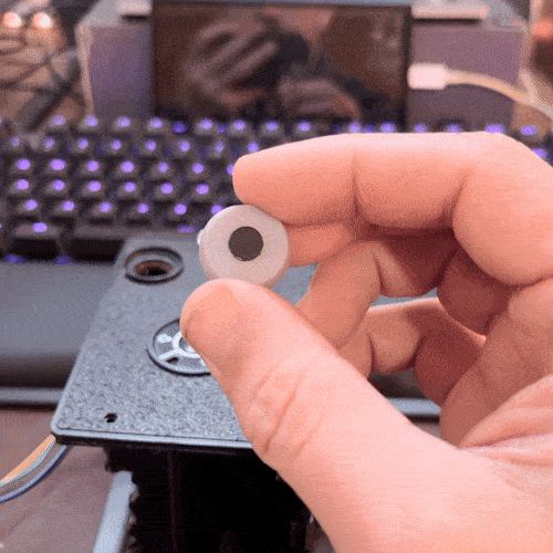
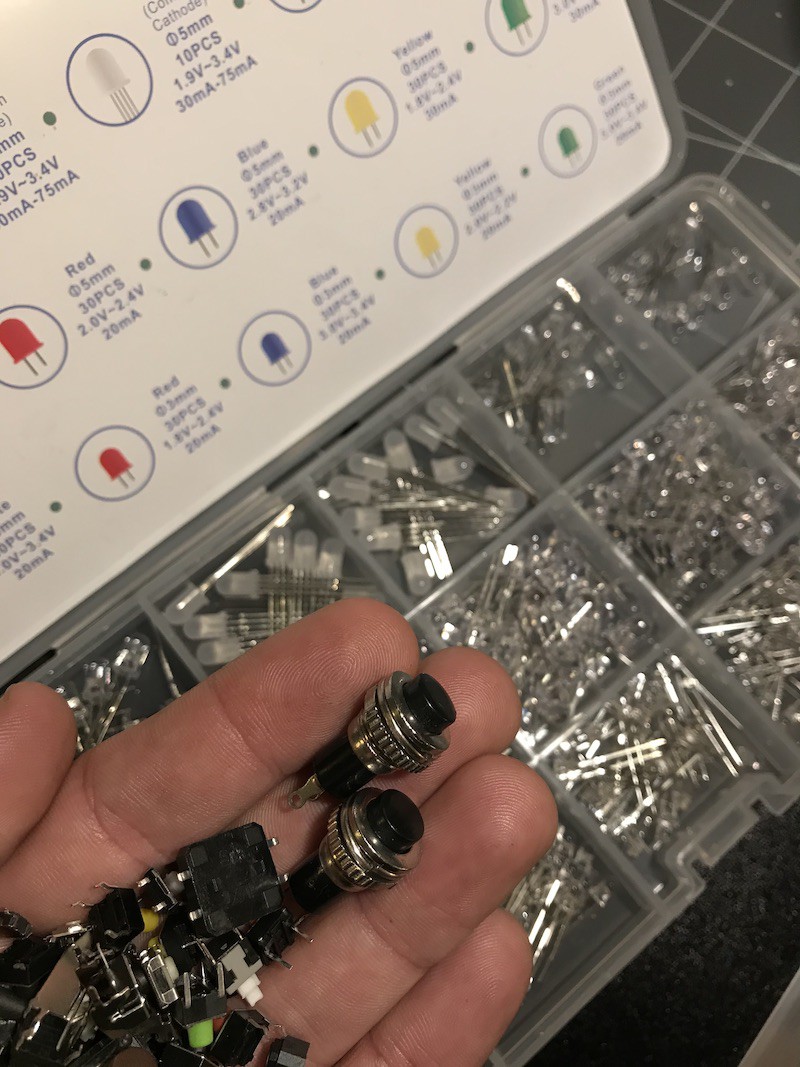
Short burst of photos saved to mp4 could be fun

  Are you sure? yes | no

Gradivis wrote 11/10/2020 at 16:21 point

I like that idea a lot! I'm considering adding a rotary dial for different modes - single photo, video, black and white and that could be a fourth. I'll have to read up on how to code that, but I think would be all the functionality required. Thanks for the idea!

  Are you sure? yes | no

Similar Projects

Does this project spark your interest?

Become a member to follow this project and never miss any updates