This project is sponsored by JLCPCB - Printed Circuit Board Factory.
Introduction
The use of sensors programmed by means of Arduino in Arduino robot is present in several competitions known as competitions for line follower robot, and this article refers to the development of a circular-shaped Arduino robot that uses two sensors programmed by means of Arduino Uno.
Among some specific rules for each competition, there is a limitation of the electronic devices that can be used, as well as the microcontrollers involved in the signal processing.
In these competitions, the competitors develop a small Arduino robot capable of following a specified trajectory through a lane, guiding it from the starting line to the finish line.
Depending on the Arduino robot competition, the rules may only allow the use of sensors and a processing platform, or may even allow the implementation of advanced programming through PID controllers (proportional, integrative, and derivative), which is a tool capable of correcting almost instantly the route the line follower robot is taking.
For the automatic detection of the trajectory, an electronic device capable of emitting different wavelengths (which characterizes each color of the rainbow) is used, thus allowing it to be guided as long as the route meets some necessary configurations.
In this way and by means of Arduino and other electronic devices, the line follower robot will be able to correct its trajectory automatically, and for the previous detection of any obstacle in front of the Arduino robot, an ultrasonic sensor was also implemented.
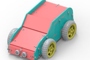
Figure 1 illustrates a line follower robot model using some electronic devices.

In the development of this didactic Arduino robot, the line follower infrared sensor (IR) was used, the ultrasonic sensor, two dc motors as well as their wheels, two casters, the motor drive, and the Arduino Uno.
The structure of the Arduino robot was designed in order to support the infrared (IR) sensor module, which will emit a signal if there is variation between white and black, which depending on the path configuration, one will be the color of the strip describing the path, and the other will be the color of the outer region.
After that, Arduino will be responsible for driving the right or left motor drive when there is a curve, or when the car leaves the path. And If something is blocking the robot's path, the ultrasonic sensor will be responsible for detecting it.
In addition, the casters ball will be responsible for maintaining the balance of the Arduino robot, helping it to move.
In this article, you will understand the assembly of the Arduino robot, as well as know its mechanical structure, which was fixed by means of the set nut bolt, in its specific fittings.
Therefore, through this article you will learn:
- Know the structure of the Arduino line follower robot using the infrared (IR) sensor module, the ultrasonic sensor, the motors, and their drivers, two wheels and two casters;
- Analyze the fixation of the mechanical structure of the case by means of screw, nut, and fittings.
- Understand the importance of each part of the Arduino robot structure for the project as a whole.
- Understand the operating logic of the Arduino line follower robot.
Now, we will start the full presentation of the development of the Arduino Line Follower Robot.
Line follower Robot development process
This project consists of presenting a didactic robot from a line follower robot car using basically the sensor modules, the ultrasonic sensor among other components, as well as the assembly of its mechanical structure.
The project is basically constituted by a physical structure of circular shape responsible for supporting the electronic components, which will process the signal to make the robot move according to the path it must follow. Figure 2 illustrates the robot's internal region.

In its internal structure, it is possible to observe the two IR sensor modules on the...
Read more »
 oblu.io
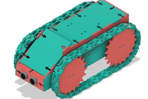
 Jithin Sanal