This article was produced in partnership with the company JLCPCB - Printed Circuit Board Factory.
Introduction
In the field of robotics, electronics, or electrical engineering, line-following robots are well known due to the competitions that encourage learning in this medium.
Each competition has its rules, which specify the level of programming and electronics with which the robots must present themselves.
The rules specify among the electronic components that may or may not be integrated into the robot, and depending on how the assembly will be made, and what equipment will be used, the developed programming may or may not be advanced.
Depending on the devices that are used, the better is to develop a structure that behaves in the best possible way.
Among the devices that can be part of the development of the robot, are the infrared (IR) sensors, the drive for the motors, the ultrasonic sensor, and the Arduino development platform. Figure 1 illustrates a line-following robot model using some of the aforementioned electronic devices.
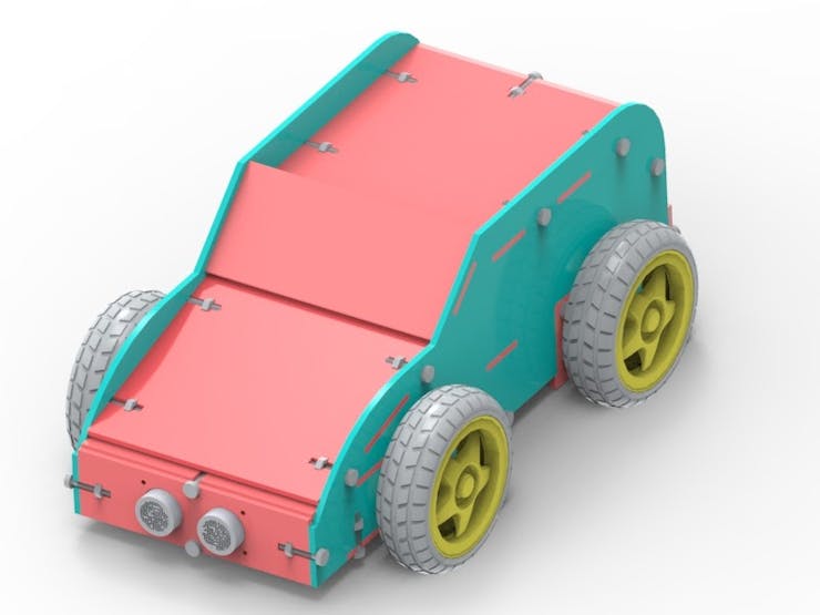
In the development of this teaching robot, two line-tracking infrared (IR) sensor modules were used, the ultrasonic sensor, 4 dc motors, 4 wheels, the motor drive, and the Arduino UNO.
The Arduino robot car structure was developed to support the IR sensor modules, which will emit a signal when there is variation between white and black, which depending on the path configuration, one will be the color of the strip describing the path, and the other will be the color of the outer region.
In this context, the Arduino will be responsible for driving the motor drive, controlling its straight path, and when there is a curve, or when the Arduino robot car leaves the path. And if there is an obstacle in the path of the robot, the ultrasonic sensor will be responsible for detecting it.
In this article, you will understand the assembly of the robot, as well as know its mechanical structure, which was fixed by means of fittings and the set of screw and nut.
Therefore, through this article you will learn:
- To know the structure of the Line Follower Robot using the infrared (IR) sensor module, the ultrasonic sensor, the wheel motors, and their drive and the Arduino Uno;
- To analyze the fixation of the mechanical structure of the robot's case by means of screw, nut, and fittings;
- To understand the importance of each part of the robot structure for the project as a whole.
- Understand the operating logic of the Line Follower Robot.
- Now, we will begin the complete presentation of the development of the Line Follower Robot.
Project Development Methodology
This project consists of presenting a didactic robot from a line-following Arduino robot car using the IR sensor modules, the ultrasonic sensor among other components, as well as the assembly of its mechanical structure.
The project is basically constituted by a physical structure similar to a simple vehicle, responsible for supporting the electronic components that will process the signal to make the robot move according to the path it must follow. Figure 2 illustrates the robot's internal region.
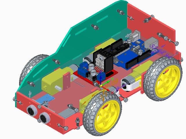
In its lower internal structure, it is possible to observe the two IR sensor modules at the base of the robot, as well as the 4 motors and their respective wheels. On the sides of each engine, auxiliary fittings were used to secure the engines to the vehicle's lower and upper internal bases.
Fittings designed for M3 nuts and bolts were designed to fix the structure.
The M3 screw has a better size for this type of project, as a size above or below this, could increase the weight of the prototype from unnecessary outside, or make it more fragile, respectively. Figure 3 illustrates the inner and outer surfaces of the robot.

The motor driver is the electronic device Motor Driver Module bridge-H-L298N, which is responsible for regulating the electric current intended for operation, activating, or disconnecting them as desired by the...
Read more »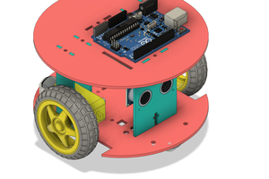
 Toni Paunovic
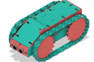
 oblu.io