This article was produced in partnership with the company JLCPCB - Printed Circuit Board Factory.
Introduction
In the field of robotics, electronics, or electrical engineering, line-following robots are well known due to the competitions that encourage learning in this medium.
Each competition has its rules, which specify the level of programming and electronics with which the robots must present themselves.
The rules specify among the electronic components that may or may not be integrated into the robot, and depending on how the assembly will be made, and what equipment will be used, the developed programming may or may not be advanced.
Depending on the devices that are used, the better is to develop a structure that behaves in the best possible way.
Among the devices that can be part of the development of the robot, are the infrared (IR) sensors, the drive for the motors, the ultrasonic sensor, and the Arduino development platform. Figure 1 illustrates a line-following robot model using some of the aforementioned electronic devices.
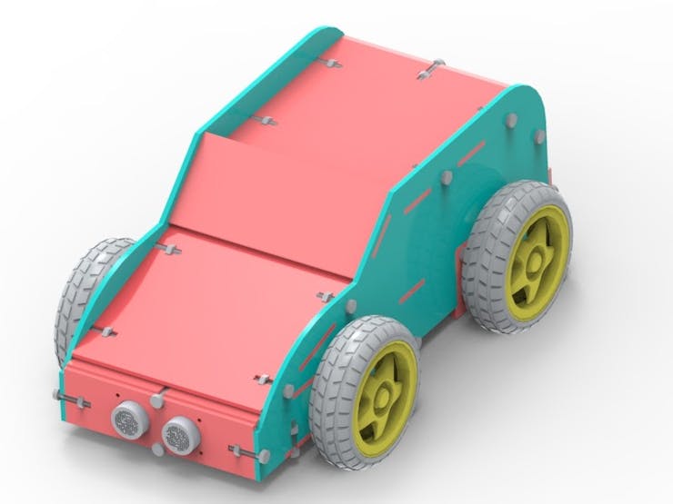
In the development of this teaching robot, two line-tracking infrared (IR) sensor modules were used, the ultrasonic sensor, 4 dc motors, 4 wheels, the motor drive, and the Arduino UNO.
The Arduino robot car structure was developed to support the IR sensor modules, which will emit a signal when there is variation between white and black, which depending on the path configuration, one will be the color of the strip describing the path, and the other will be the color of the outer region.
In this context, the Arduino will be responsible for driving the motor drive, controlling its straight path, and when there is a curve, or when the Arduino robot car leaves the path. And if there is an obstacle in the path of the robot, the ultrasonic sensor will be responsible for detecting it.
In this article, you will understand the assembly of the robot, as well as know its mechanical structure, which was fixed by means of fittings and the set of screw and nut.
Therefore, through this article you will learn:
- To know the structure of the Line Follower Robot using the infrared (IR) sensor module, the ultrasonic sensor, the wheel motors, and their drive and the Arduino Uno;
- To analyze the fixation of the mechanical structure of the robot's case by means of screw, nut, and fittings;
- To understand the importance of each part of the robot structure for the project as a whole.
- Understand the operating logic of the Line Follower Robot.
- Now, we will begin the complete presentation of the development of the Line Follower Robot.
Project Development Methodology
This project consists of presenting a didactic robot from a line-following Arduino robot car using the IR sensor modules, the ultrasonic sensor among other components, as well as the assembly of its mechanical structure.
The project is basically constituted by a physical structure similar to a simple vehicle, responsible for supporting the electronic components that will process the signal to make the robot move according to the path it must follow. Figure 2 illustrates the robot's internal region.
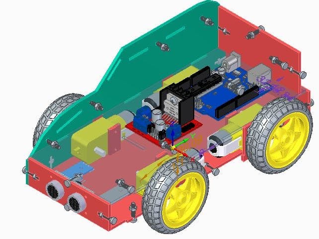
In its lower internal structure, it is possible to observe the two IR sensor modules at the base of the robot, as well as the 4 motors and their respective wheels. On the sides of each engine, auxiliary fittings were used to secure the engines to the vehicle's lower and upper internal bases.
Fittings designed for M3 nuts and bolts were designed to fix the structure.
The M3 screw has a better size for this type of project, as a size above or below this, could increase the weight of the prototype from unnecessary outside, or make it more fragile, respectively. Figure 3 illustrates the inner and outer surfaces of the robot.

The motor driver is the electronic device Motor Driver Module bridge-H-L298N, which is responsible for regulating the electric current intended for operation, activating, or disconnecting them as desired by the specific programming developed in Arduino UNO. The robot for this project has 4 wheels with 4 engines each.
This driver can control from the speed of the robot wheels through the PWM pins of the Arduino, up to the direction of rotation, being able to control up to two dc motors, or a stepper motor. The driver was fixed to the upper inner surface, as shown in Figure 3.
The robot also has on its lower internal surface, two IR TCRT5000 sensor modules, which were placed in the central region, with the necessary distance for greater coverage of the ground where it will have an indication of the route through a strip.
The IR sensor used is digital, that is, it acts by detecting the values "0" or "1", and sends a signal of the low logic level (for the value "0") or high signal (for the value "1" ”), And in this way, the robot will react according to the implemented programming. Figure 4 illustrates both the motors and the IR sensors.

In addition to the line follower IR sensor modules, the ultrasonic sensor was also implemented, responsible for detecting the presence of objects that are in front of the robot.
Through this sensor, it will be possible to make the robot deviate its trajectory if an obstacle is detected, as this sensor emits sonic bursts that when in contact with an object, the signal is reflected back to the sensor, which in turn sends a signal to the Arduino, which through its programming, it is possible to develop an appropriate reaction for the robot.
For the fixation of the ultrasonic sensor, a structure was modeled to fix it to the lower and upper internal surfaces. In addition to fixing the sensor, this structure also has the function of "locking" the side structures of the robot. Figure 6 illustrates the position of the ultrasonic sensor in the line-following robot.

The Arduino is basically responsible for two purposes: to carry out the signal processing coming from the line-sensing IR sensor modules and the ultrasonic sensor, and to make the necessary settings to control the motors through the driver through a control program.
The Arduino was positioned in the rear region of the robot, in order to facilitate the programming developed and the possible changes, being necessary only to fit the power and USB communication cables, without the need to remove the Arduino from the robot's case. Figure 6 illustrates the position of the Arduino in the line follower robot.

Figure 7 illustrates the entire structure of the line-following robot in an exploded perspective of the main parts in a rendered image.
Next, we will discuss the programming logic process that should be used for programming the Arduino robot car.
Arduino robot car programming logic
The robot's operating principle is based on line-following sensors, which, depending on the runway configuration, will detect the presence or absence of a black or white band.
The IR sensor modules will detect the range, and when the robot moves out of the path described by the range, the sensors will send a signal to the Arduino indicating the variation in the detection of the black, or white color, which will be the color of the range.
When this happens, the Arduino will start the necessary engine so that the path is corrected as soon as possible.
When the path has curves, the IR sensor modules will work in the same way, decelerating the necessary motors so that it is possible to make the curve in the desired direction.
The ultrasonic sensor in front of the robot will detect the presence of an obstacle along the way, and if it does, a signal will be sent to the Arduino, which, through its programming, will correct the path to avoid the object.
The control board for the Arduino robot car
The JLCPCB wants to offer 5 units of this Arduino JLCPCB compatible PCB for your projects for $2 in your first order with the link: Earn my PCBs Arduino Compatible.

Conclusion
We conclude that the main parts of the structure were checked and analyzed in order to better understand the importance of correct assembly, observing the function (according to the structure where it was fitted) of each component.
Therefore, from the development of the line-following robot project, it was possible to analyze its mechanical structure, optimizing the available spaces. The robot's structure was modeled with M3 fittings and screws for its fixation, and thus, creating better mechanical stability, favored by the rear and front structures, which connect the other structures.
All its development was done with the purpose of making it as didactic as possible for its subsequent assembly with the electronic part.
Files for assembly of the Arduino Robot Car
All the files presented below are used for you to perform laser cutting with a 2.5 mm thick plywood.
Access and download of the files.
Acknowledgments
We thank the company JLCPCB - Printed Circuit Board Factory for the support and partnership in the development of this project.