 Mitsuru Yamada
1. Hardware
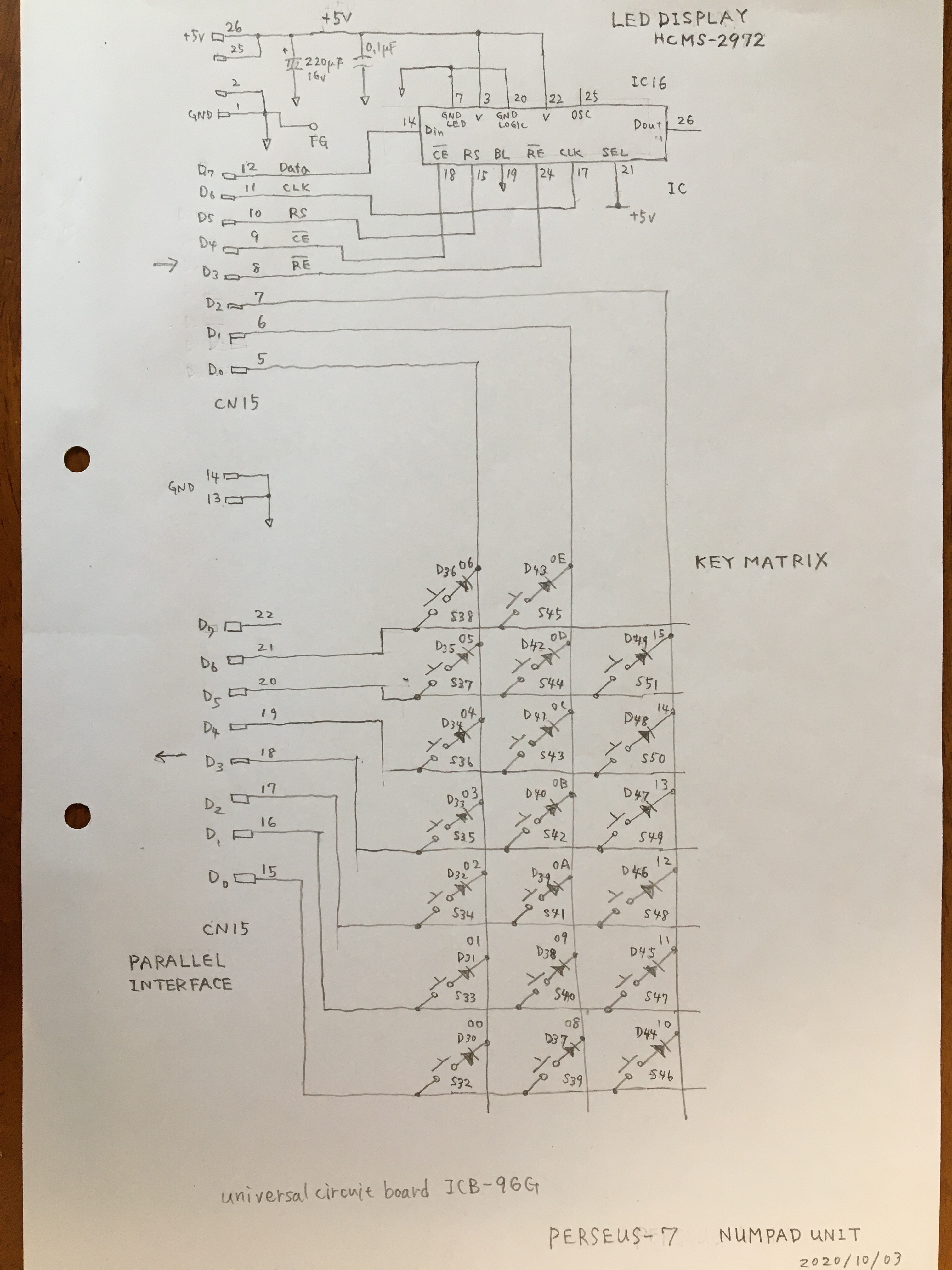
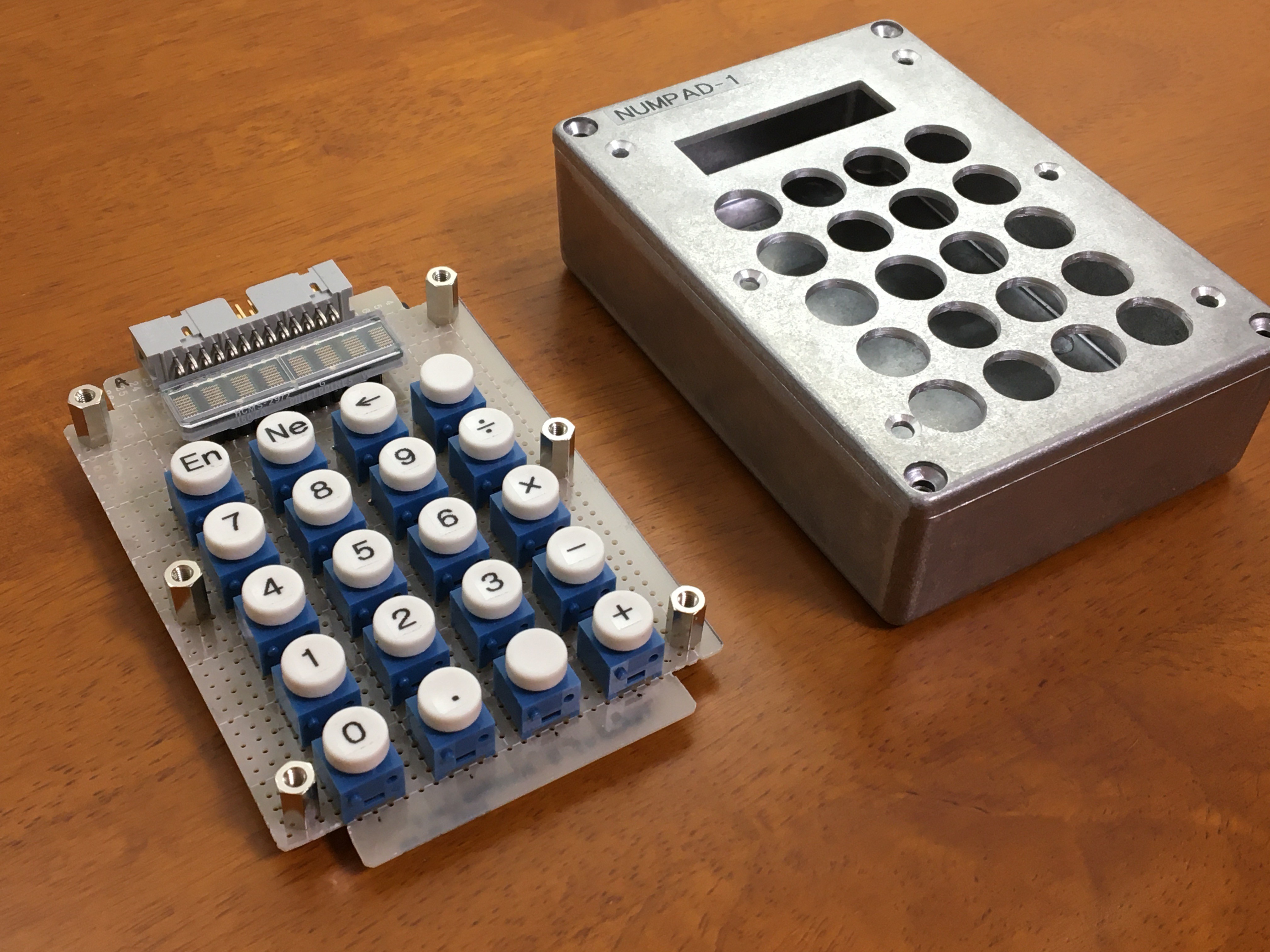
This calculator is configured with a numpad unit connected to the computer shown in the project “6502 standalone computer". The numpad unit consists of an LED display (HCMS-2972, BROADCOM) and a key matrix as shown in the circuit diagram. The HCMS-2972 is an 8 characters 5 x 7 dot matrix alphanumeric display. This device requires serial input of character font patterns. For the serial input of the display, 5 bits of the output port of the parallel interface are used. Three bits of output port are used for scanning the key matrix, 7 bits of input port are used to read the key scan result. The numpad unit uses 12 cm x 9 cm x 3.5 cm aluminum die-cast housing.
2. Software
2-1. Key scanning and conversion to BCD
Key scanning is performed by a reading of row data of the key matrix during each column is applied a low level logic as shown in schematic. When that key is pushed, the row data will be a low level. The read pattern data is converted to a byte numerical code in the table. Two numerical codes are combined to an 8bit BCD. Each BCD is applied to an appropriate digit position of the 128 bits RPN stack register. This process is described in the part after address $10E in the source code.
2-2. BCD addition and subtraction
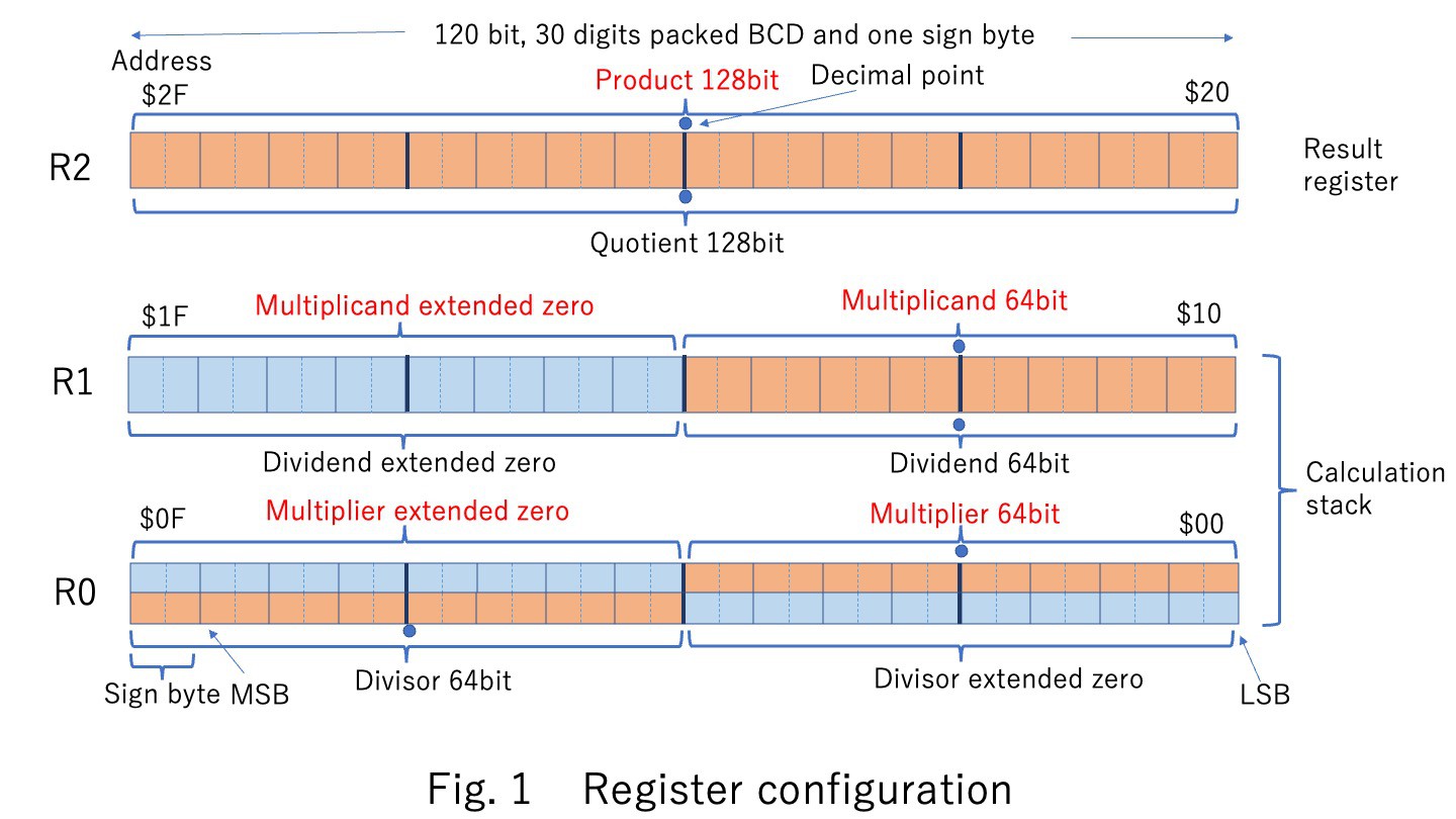
The calculation input values are R0 and R1 in Fig.1 below, and the results are stored in R0. Signed absolute values of the calculation registers are converted to decimal compliments. An addition and a subtraction are performed a decimal complement using 6502’s ADC or SBC instructions. After that, a result is converted to a signed absolute value. This process is described in the part after address $31B in the source code.
2-3. BCD multiplication and division
The signed absolute values of the calculation registers are separated to signs and absolutes. A multiplication or a division is performed with absolutes. The sign is calculated separately and finally combined with the result. The register configuration for multiplication and division is shown in Fig. 1.
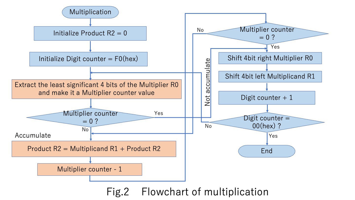
For multiplication, extracting a one digit of the multiplier and accumulating the multiplicand by that number obtain a partial product of multiplication. The calculation is completed when this process is repeated to the most significant digit. Figure 2 shows the flowchart of this multiplication. This process is described in the part after address $20B in the source code.
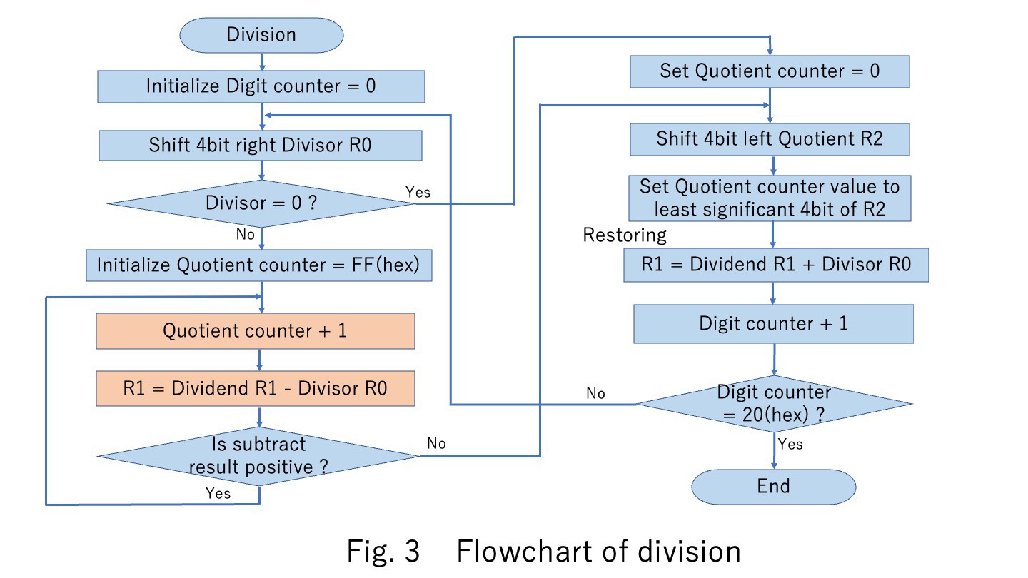
For division, restoring method is used. The quotient is calculated from the number of times the divisor is subtracted from the dividend until the result becomes negative. The negative dividend is recovered by adding the divisor once. The divisor is shifted right by 4 bits. Figure 3 shows the flowchart of this division. This process is described in the part after address $260 in the source code.
2-4. Sending character font to LED display
The 128 bits BCD calculation result is extracted to 6 digits numeric codes. The display digit position can be changed. The numeric code is converted to address of the numeric font table. Extracted font data is serialized and send to the LED display device. This process is described in the part after address $382 in the source code.
3. Result
Debugged program size reached total 992 bytes of machine codes. Four arithmetic operations can be performed correctly, but zero suppression and rounding is not implemented due to a limit of memory size. RPN stack is only two levels. Since it takes a long time to input a long program like this with toggle switches, I made an external ROM module. This will be reported later.
Reference: HCMS-29xx Series High Performance CMOS 5x7 Alphanumeric Displays Data Sheet, AVAGO TECHNOLOGIES
Related articles:
https://hackaday.io/project/175866-6502-standalone-computer
https://hackaday.io/project/175923-rom-module-for-6502-standalone-computer
https://hackaday.io/project/175924-fully-manual-prom-programmer
Video:
(Rev. May 19, 2022)