0%
0%
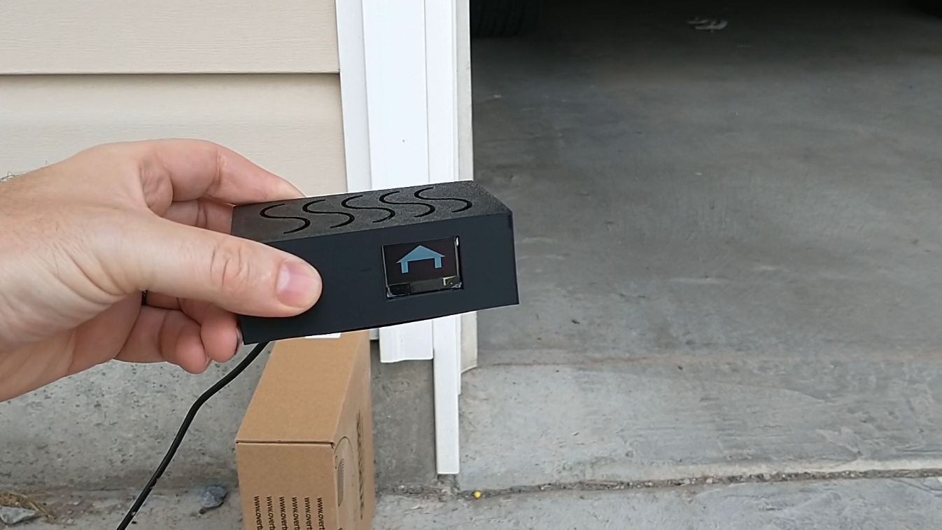
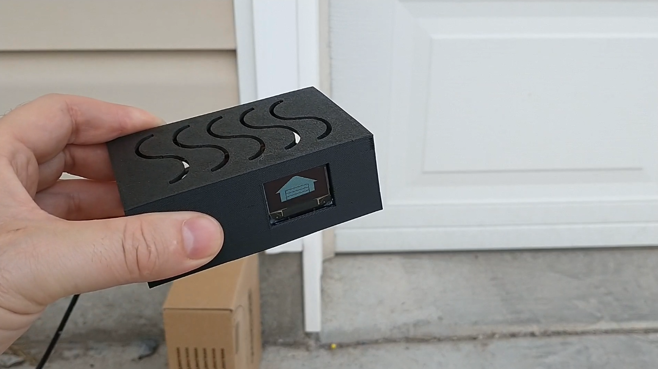
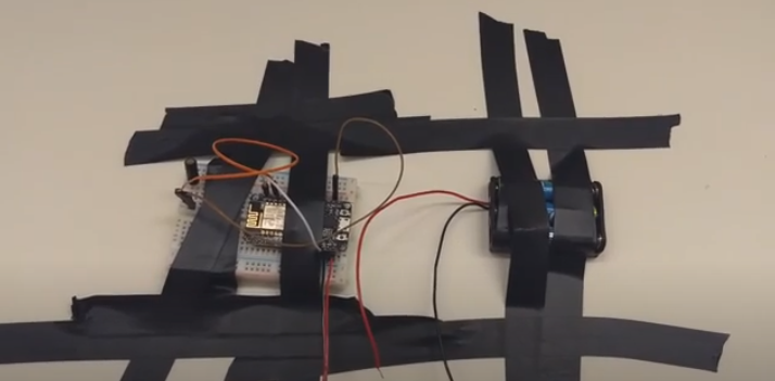
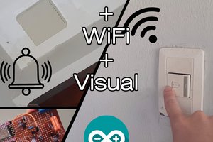
Garage Door Left Open Detector
A simple device to notify me when I leave my garage door open.
 ThinkLearnDo
Become a Hackaday.io member
Already have an account? Log in.
Just one more thing
To make the experience fit your profile, pick a username and tell us what interests you.
Pick an awesome username
hackaday.io/
Your profile's URL: hackaday.io/username. Max 25 alphanumeric characters.
Pick a few interests
Projects that share your interests
People that share your interests

 Octavio.Makes
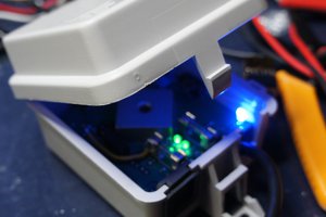
 KingOfKYA(Travis K. )
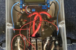
 Nick Sayer
 Mastro Gippo
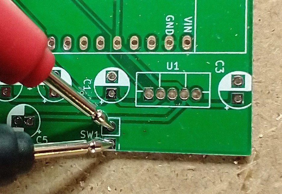
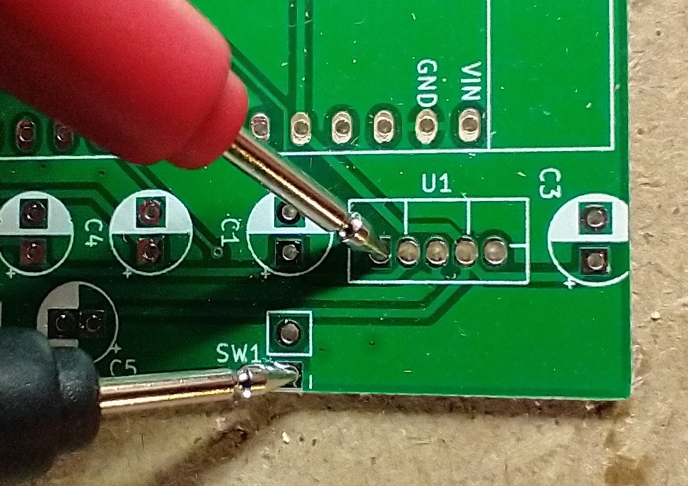
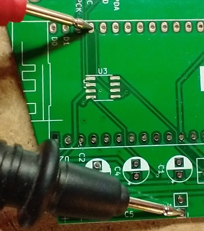
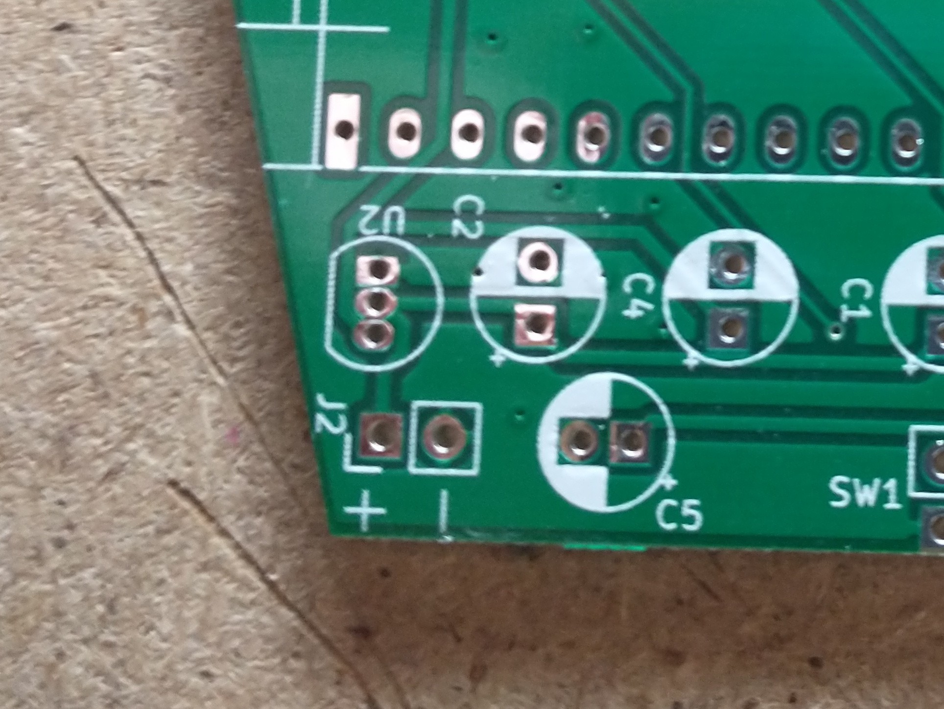
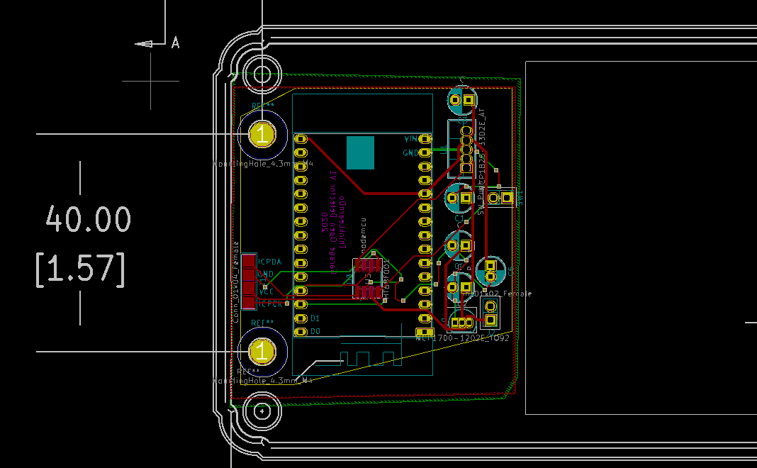
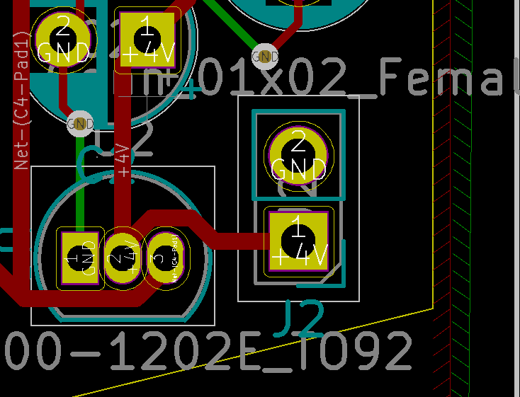
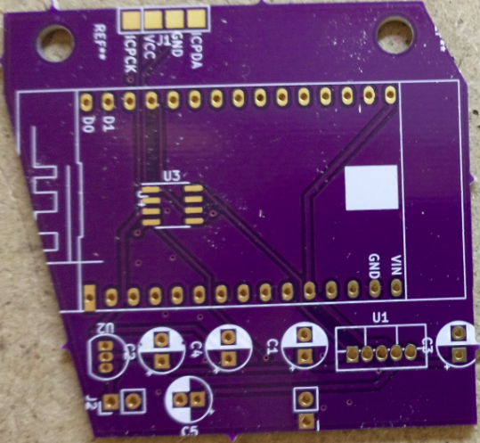
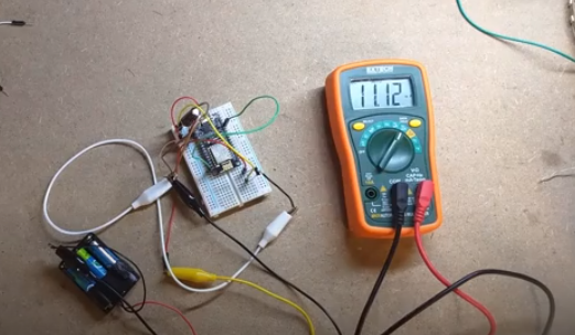
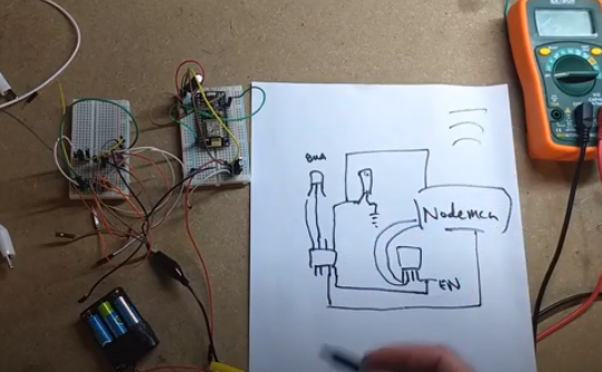
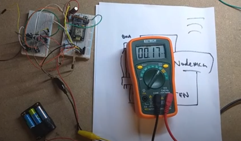
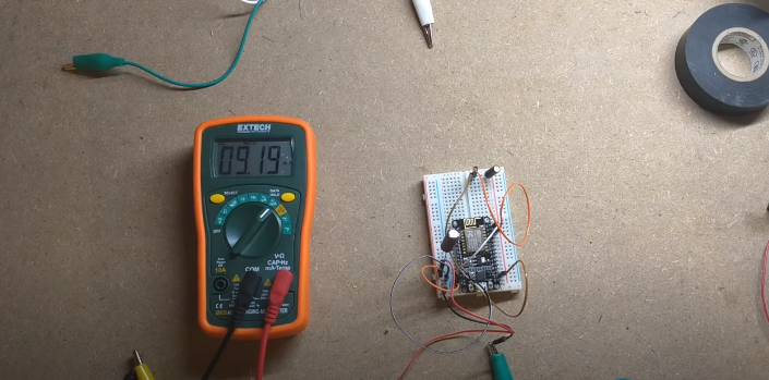
You can check my complet Garage Door System on my profile if you want, I used a 230V converter but for test it can be powered by the microUSB of nodeMCU PCB