-
Adding a garage door state indicator with raspberry pi + oled
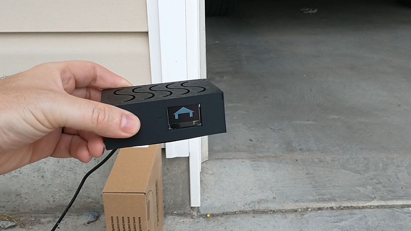
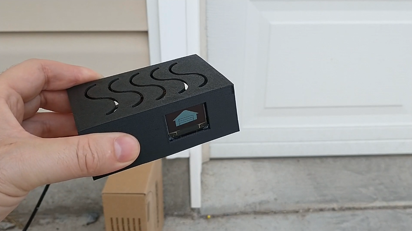
08/05/2022 at 23:21 • 0 commentsI've loved getting emails from my garage door notifier, but I wanted something that I could just look at and know the state of the garage door. Enter the Garage door state indicator! Since my server is written in nodejs, I went with a raspberry pi + oled combo. Then stuck it in a nice black 3d printed case.
![]()
Hey look the doors open!
![]()
And closed :).
project files, code and assembly notes are on my github: https://github.com/thinklearndo/garagedooropennotifier
Also see it in action: -
More customer feedback... With batteries dying too fast
05/06/2021 at 04:48 • 0 commentsHad a problem from a customer the other day. The batteries in his garage door left open notifier were getting drained really fast, like in a week. The batteries should last a year! We dug into it and found the problem: a solder bridge on the U2 voltage regulator.
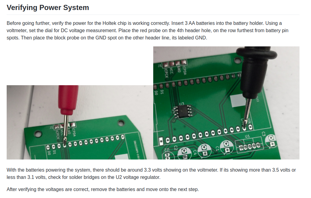
I pulled out the nodemcu and checked voltages with a fresh set of batteries. I checked the voltage on the header at the spot where D4 plugs in, and it was reading 4.5 volts, which is way high. It should be 3.3 volts. That pointed to something strange with the voltage regulator U2, which feeds the holtek. Visually inspection showed that there was a solder bridge between the input and output pins of the voltage regulator, so we removed that. Checking again after it was out showed there was still a bridge on those 2 pads. Scraping around those pads fixed that, but I was worried that putting a new voltage regulator back in the same spot would just recreate the bridge. To avoid that we jury rigged it, and I was so ashamed of the outcome that I didn't even take a picture to put on this blog post ;).
Testing showed that it was back to 3.3 volts on the D4 pin spot which was a good sign. We assumed it burned out the D4 pin, so we replaced the NodeMCU with another one and it worked good as new!
To make sure that the board is assembled correctly, I added some more info to the Hardware Assembly page, it now shows how to verify the operation of the U2 voltage regulator:
![]()
-
Improving My Assembly Documentation
03/25/2021 at 04:32 • 0 commentsOne of my end users had some confusion about why his kit wasn't working. Worked through the issue with him, turned out he mounted it backwards on the garage door.
Good way to find out my documentation is lacking :).
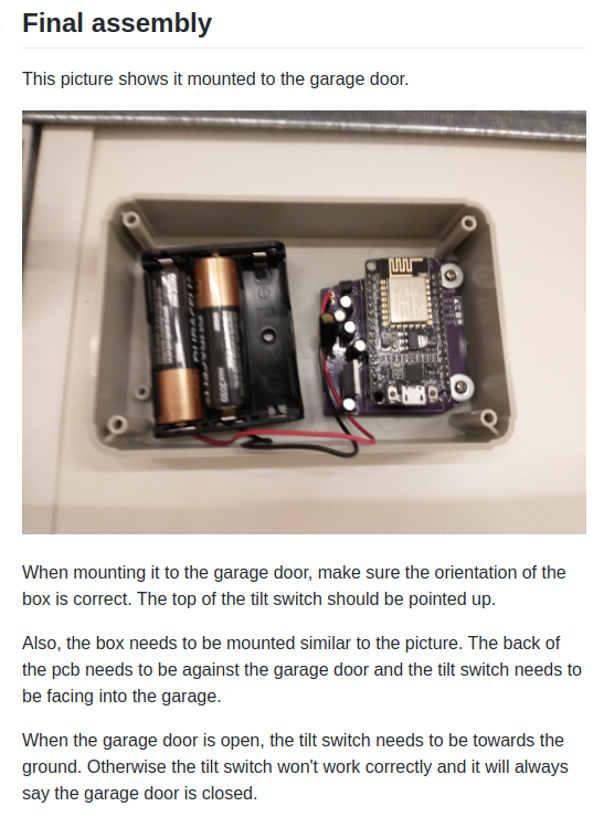
Updated my assembly doc to make it more clear about how to mount it on the garage door. That's definitely a downside to this kit, it requires it to be mounted a very specific way in order for it to detect if the door is open or closed.
Here's my new version:
![]()
Previously it said something like make sure the switch is pointed up and stick it on the door.
-
QA'ing the kit
03/17/2021 at 21:15 • 0 commentsI've actually managed to sell a few kits, so that's exciting.
As I was getting them ready to sell, I wanted to make sure the little holtek chip on there was soldered on and working correctly. So I needed a some Quality Assurance to make sure I was sending out working stuff.
I came up with the following steps after I flash the holtek and power it up through the flashing tool to verify its operation:
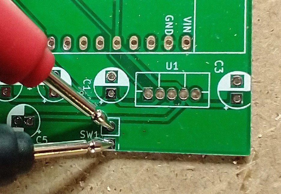
1. Check that the pull up for the tilt switch is working. Get the multimeter and set it to voltage. Then press the black probe to the ground pin of SW1 and the red probe to the pull up side of SW1. It passes if it registers 3 volts.
![]()
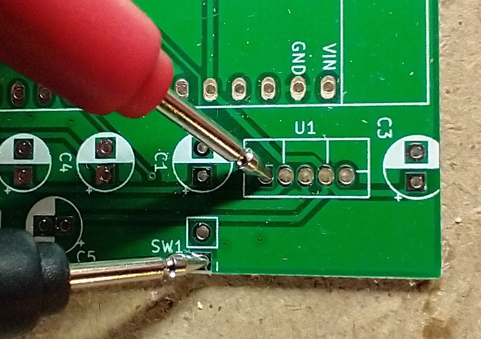
2. Check that the enable pin for the Voltage regulator that feeds the nodemcu, U1, is off. The holtek chip should wait for the state of SW1 to change before it turns on the voltage regulator. Press the red probe to the enable pin of U1, the far left pad. This test passes if the multimeter reads 0 voltage or ground.
![]()
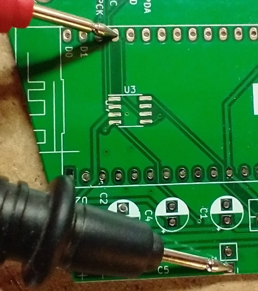
3. The next pin to check is the one the holtek uses to check if the nodemcu is done. Its labeled D3 on the nodemcu. That pin is set to input pullup on the holtek so it should read 3 volts. Take the red probe and place it on the D3 pin spot. Test passes if its 3 volts.
![]()
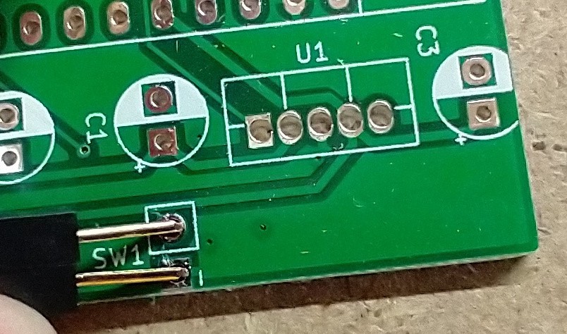
4. Now to check that a state change on SW1 will trigger the holtek to turn on the Nodemcu's voltage regulator, U1. Short the pads for SW1 with a jumper wire for several seconds and remove it. Now take the black probe and red probe and place them according to test 2. This time it should show 3 volts and that passes the test.
![]()
That gives me pretty good confidence that the holtek chip is soldered on correctly and programmed correctly.
The final test I could do, where pulling the D3 pin low will turn off the U1 voltage regulator, and I've done that on some of the boards. It doesn't seem to add much to the testing. It would find a software defect on the holtek but I've already proven that out, so it doesn't need to be done every board.
-
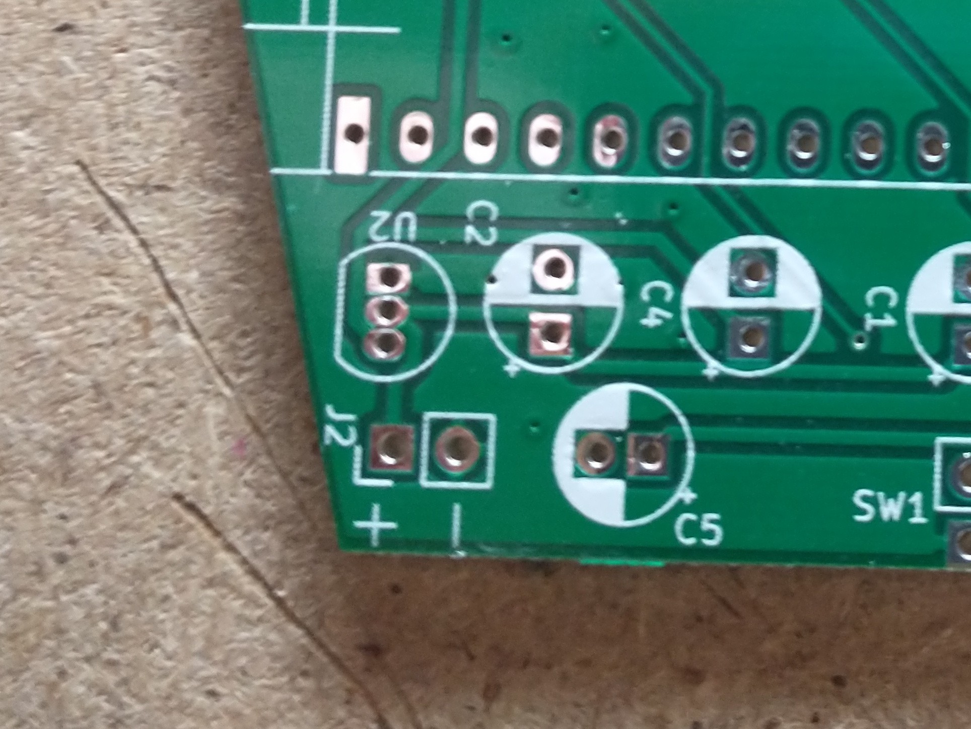
New board version with fixed screw holes and power markings
03/10/2021 at 05:46 • 0 commentsI got back my fixed boards and now they have correct power markings! No more guessing on that :)
![]()
I also remembered to put the SW1 marking for where the tilt switch goes, so that was a nice fix as well.
For my mounting holes, I found out my raspberry pi's mounting holes were about the right size for the screws that came with my case. They were about 2.9mm in diameter. I created a new mounting hole in kicad with the right diameter and replaced the old ones. Testing them was a success! So I think this board is pretty much finished.
-
Making the circuit board
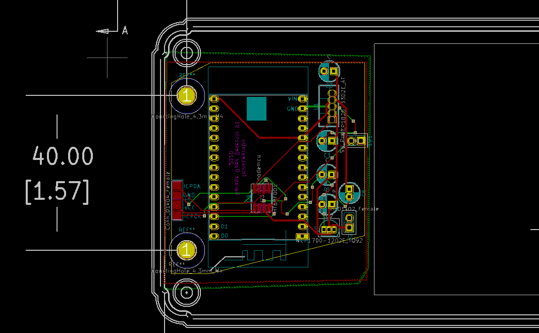
02/18/2021 at 03:11 • 0 commentsI used Kicad to put my first version of the circuit board together. I wanted to have this fit a case I found on mouser, so I needed to come up with a way to make sure the mounting holes would fit the case.
Luckily the webpage for the case I picked out, https://www.hammfg.com/part/RL6215, had a dwg version of the case. I took that and coverted it into a dxf file, which I was then able to import into PCBNew. Then when I put in the mounting holes, I just had to make sure they lined up with the image.
![]()
After I got the boards I was happy the holes match up correctly. Sadly, I made the mounting hole too large. I had to use some washers to make sure the screws wouldn't pull through. I'll have to fix that on the next revision.
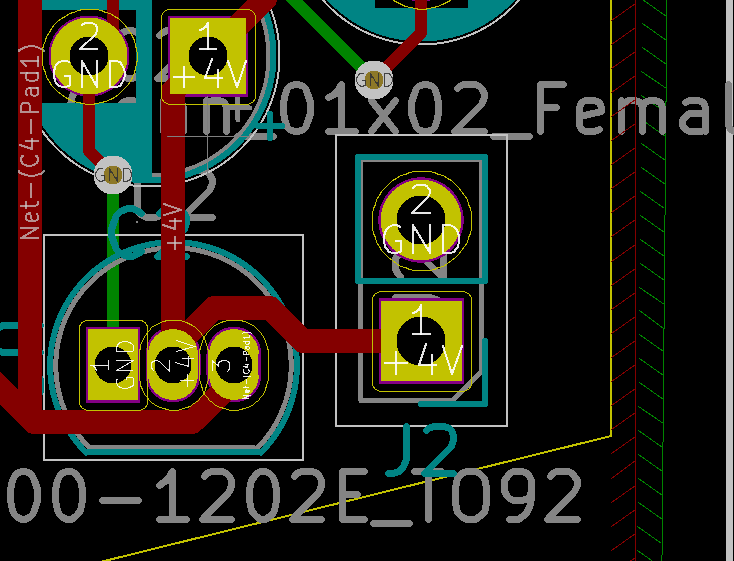
Another thing I screwed up on this board version, was I forgot to mark the + and - on the battery connector spot.
![]()
So thats another thing I'll have to fix on the next board revision.
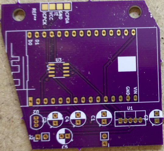
All in all I'm pretty happy with how the board turned out.
![]()
Next up I'll need to get it assembled and try it out.
-
Prototyping part 2
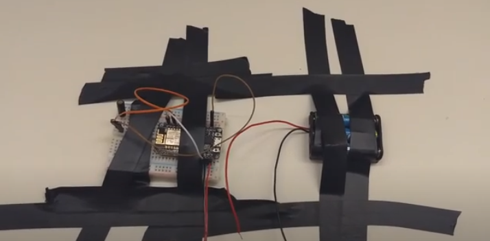
02/10/2021 at 01:34 • 0 commentsI went ahead and tested it by sticking it on my garage door with electrical tape.
![]()
Very classy :).
It did work though, that was exciting.
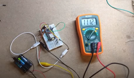
I used a different voltage regulator with a lower quiescent current or idle current draw, thinking that would solve my current draw in deep sleep woes. But no such luck.
![]()
That made it worse... Back to the drawing board.
My next idea was to do a completely different setup.
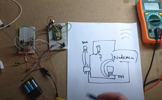
I'd been playing with a super low current microcontroller from holtek, the HT68F001. It draws like 6ua while running. My idea that I came up with is to let the Holtek microcontroller monitor the switch state and wake up or power on the nodemcu when the state changed. That way I wouldn't have to draw much power and I could continuously check the state of the switch, which was a win for some other projects I wanted to try.
So the final circuit I came up with is something like this:
![]()
If you want to see a better version check out the github page, it has a kicad version.
What the circuit is showing is the holteck and the nodemcu are both tied into the tilt switch, both using input pullup on those pins. Then theres a voltage regulator that has an enable pin that will power the nodemcu. The holtek chip has a pin going to that enable pin so it can turn on and off the nodemcu. Then theres another connection between the holtek and nodemcu, where the nodemcu can signal that its ready to shut down. And the holtek is powered by its own low quiescent current voltage regulator.
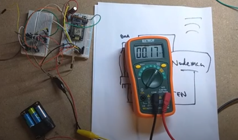
Checking the current draw with the nodemcu turned off turned out pretty good, it got down to .17 ma, or 170ua, a huge improvement.
![]()
The next steps are to get it all mounted on a circuit board and put it in a case.
-
Prototyping stage one.
02/10/2021 at 00:39 • 0 commentsI've gotten to the age where I'm forgetting things more often. And one thing that I kept forgetting was to close the garage door. This project was an attempt to make something that would remind me to close the garage door.
While trying to solve the problem, I had a simple idea. By using a ball tilt switch, ie poor mans accelerometer, I could detect what orientation the garage door was in. Then by using a nodemcu I could periodically check the state of the tilt switch and then send a message to myself if it was in the wrong position.
Writing the nodemcu code was simple enough. I set a pin to input pullup, and then every minute I would check its state. If the value read low, it meant the switch was closed and that the garage door was also closed. If the value read high, it was open.
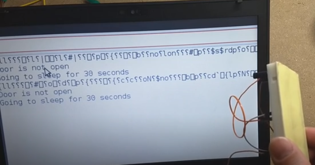
My first test seemed to go well enough. You can see here my program thinks the door is closed.
![]()
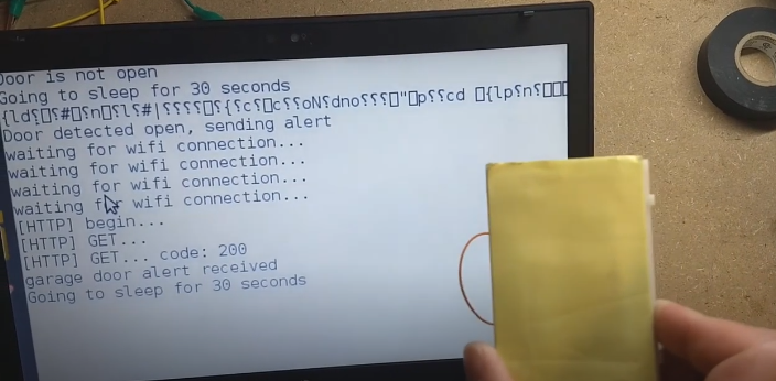
Then with the tilt switch in a upside down orientation, it detects the door open.
![]()
On the other side, I just had a simple nodejs server running to receive the alert.
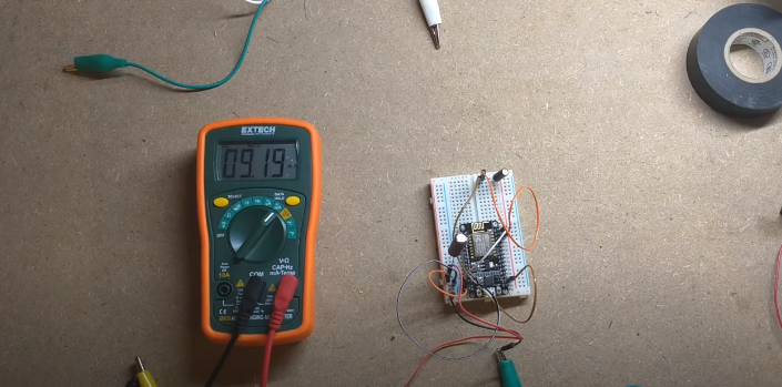
The next part I needed to figure out was power. I was planning on just hooking it up to some AA batteries but from previous projects I'd done with nodemcu's, the idle current from the nodemcu would be too high. I checked it by putting the nodemcu into deep sleep and measuring the current draw.
![]()
And I was right. Even in deep sleep its drawing ~9ma, AA batteries won't last long at that draw.
Garage Door Left Open Detector
A simple device to notify me when I leave my garage door open.
 ThinkLearnDo