 Phil Malone
Now things were working, I needed a way to mount the LEDs and electronics in a nice housing to make my Visual Ear a piece of furniture.
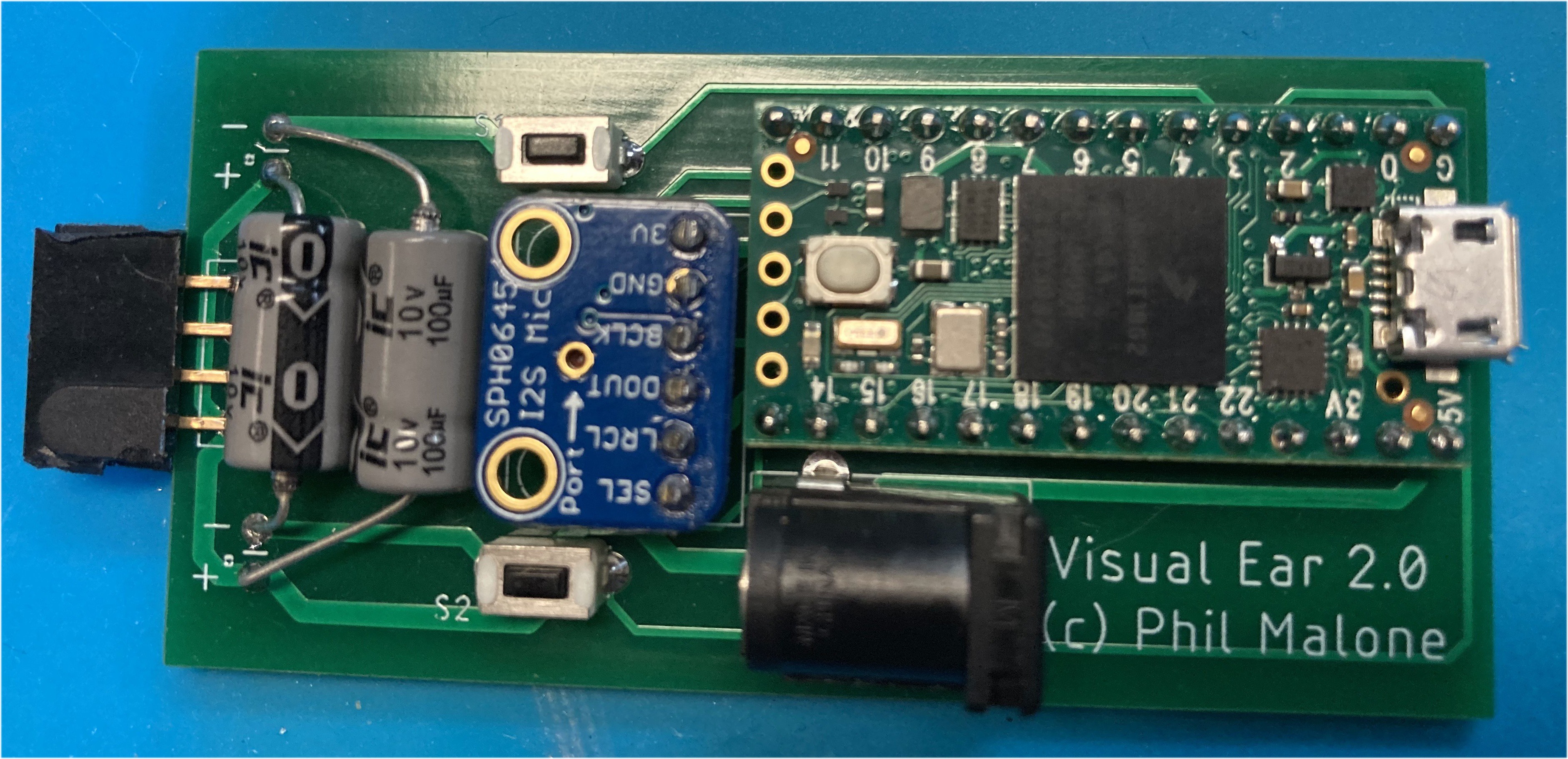
As soon as I had verified that the Teensy was a great choice for the project, I used EagleCad to design a simple PCB to hold the Teensy, Adafruit I2S microphone breakout and some switches. I then sent to files of to PCBway.com to get them turned into some PCBs.
To anyone who is still fighting with protoboards or hand-making PCBs, you REALLY need to try out PCBway. Learning a versatile schematic and layout program like EagleCad is a great investment, and then turning your ideas into clean PCBs couldn't be simpler, cheaper or faster than PCBway.
For this project I went with their 10 boards for $5 plus $27 for DHL 5-7 day shipping. The boards are made in 24 Hours and shipped from China. I typically get my finished boards within 7 days of sending the files. The customer support is pretty great considering the low costs, and then I often end up getting them to assemble low-medium quantities of boards if I'm going to sell them.
In this case, by the time I had ordered the LED mounting strip, and finished refining the design for the 3D printed end-cap, the blank PCBs turned up ready for me to assemble into the final product.
Here's the end result, with the components added.
Next was the physical mounting hardware.
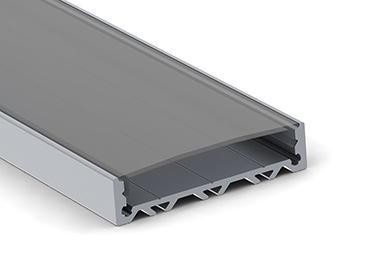
I did some research to locate wide aluminum LED mounting strips. I needed it to be wide because I wanted to make a 3D printed end-cap to house the circuit board and none of the narrow mounting strips I had found were wide enough.
I found a great strip form Wired4Signs.com that was more than wide enough to insert a printed end-cap that could hold the PCB I intended to make.
I used OnShape.com to design an end-cap to fit inside the end of the strip. The first version was just to hold the PCB and see if the microphone would work through a hole in the cover.
I used my new FLASHFORGE Adventurer 3 Printer to print a series of pieces, each verifying one design element or another. I just love the quality of the FLASHFORGE prints.
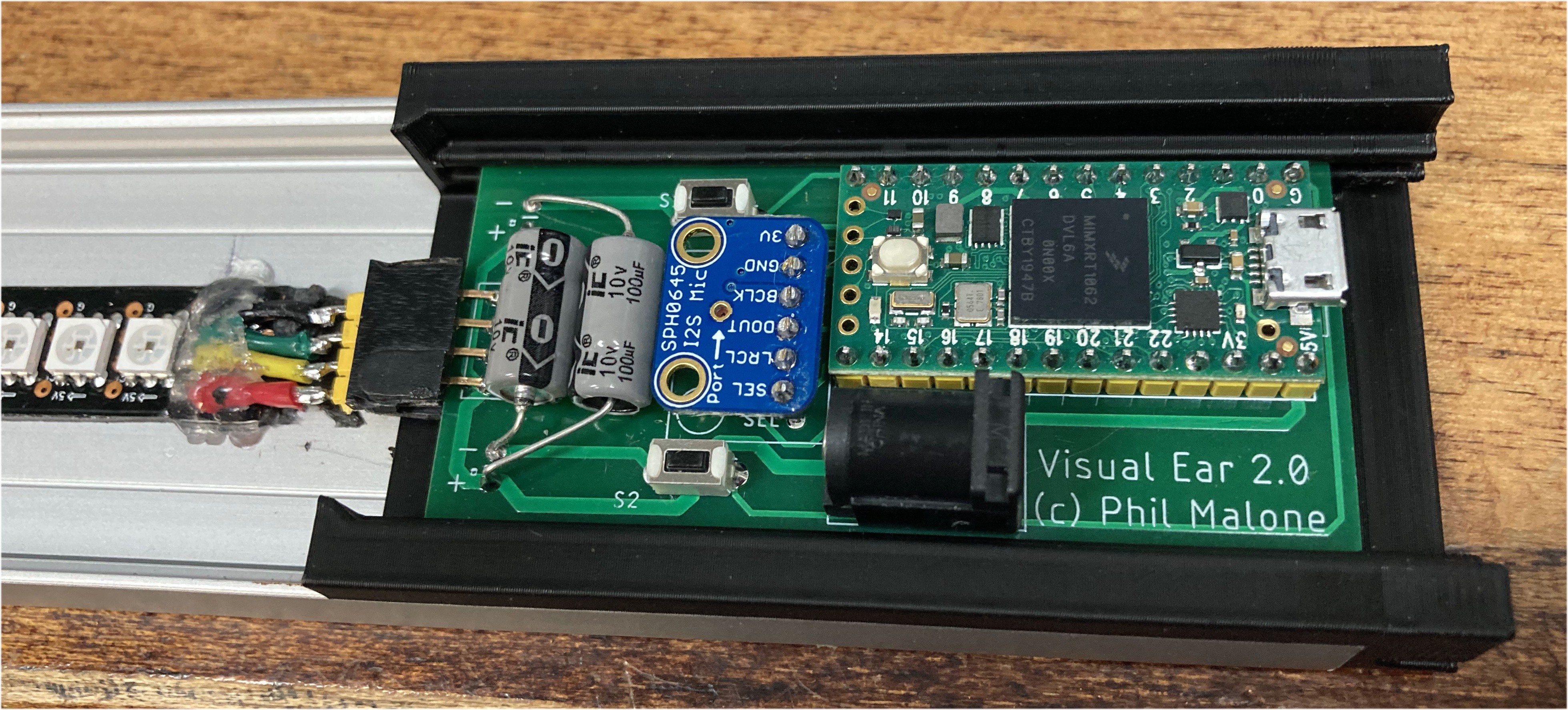
Here's the PCB slid inside the end-cap and fitted inside the end of the metal strip. Also note the high density LED strip attached to the housing, and connected to the PCB via a 4-pin plug. (Excuse the hot glue used to anchor the wires.
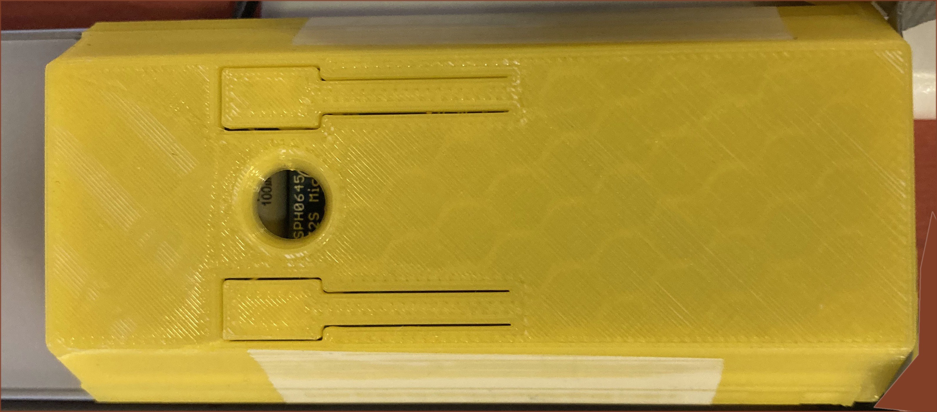
A 3D printed cover snaps over the end-cap and has two flexible button covers that flex and let you increase or decrease the microphone sensitivity.
I mounted the strip to the wall and took some photos of normal talking speech. You can get a feel for the wide range of color/tone combinations from the pics below.
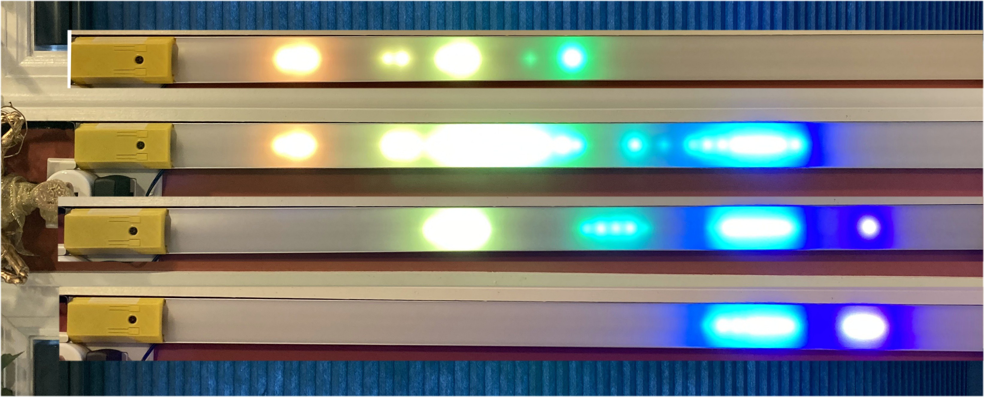
The colors extend all the way down to a deep red for very low tones, and up into violet for sounds that I can't even hear.
Discussions
Become a Hackaday.io Member
Create an account to leave a comment. Already have an account? Log In.