 Julian Calaby
At the time of writing this, I'm considering this project fundamentally complete:
- The key matrix has been re-built to contain anti-ghosting diodes
- The USB controller has been replaced with a Teensy LC
- Some relatively minor changes have been made to the non-key electronics to adapt it to these changes
- A custom keyboard matrix and layout have been built for QMK
- And that Teensy LC has been flashed with this QMK build and the QMK configuration has been tweaked a little to suit the final product
This post is going to cover the hardware side of this latest round of progress.
The Matrix
The original matrix was designed to replicate the matrix of a cheap membrane USB keyboard and as such was just point-to-point connections between switches with some flying leads to the USB keyboard's PCB. QMK can support this sort of matrix, so I could have just gotten away with replacing the original USB PCB with the Teensy LC, but that wouldn't have produced the result I was after.
Adding a diode to every key took 4 days of work.
The plan was pretty straight forward:
- Remove the original controller
- Add diodes
- Add in the Teensy LC

This is what the original matrix looked like after the controller and all it's flying leads were removed. You can see the leads in a pile in the bottom half of the case.
I also took the opportunity to label the connection point of every column and row, these are the big "C11" and "R5" labels. Note the thick sharpie marks next to some pads, this was to make it obvious exactly which pad was the connection point as there was already a lot of sharpie marks on the keyboard from the original matrix. (I believe I used these to mark connections in the original matrix once I was sure it "dealt with": either connected to the correct keyswitches or cut)
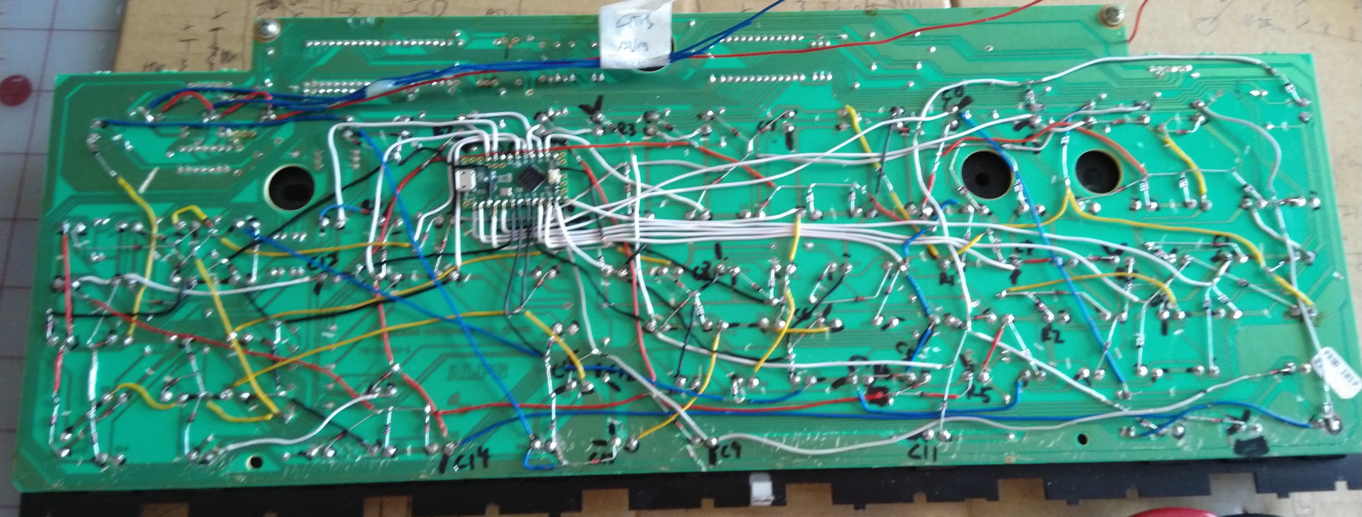
And this is what the board looked like when I was finished. I got into the groove and didn't take any progress shots.
Each keyswitch got it's own diode, however actually adding those diodes to the matrix required some level of creativity:
- Some were easy: I'd previously cut a trace on the "row" side of the keyswitch, so that pad was isolated, this just required shortening the connecting wire and adding a diode. You can see examples of this at the top right and top left.
- Some required a little extra thought: it technically doesn't matter which side of the keyswitch the diode is on, as long as it faces the correct direction, so if the pad on the "column" side of the keyswitch was isolated, then I could just stick the diode on that side instead.
- There were a few places where, through some happy accident, the connecting wire was short enough and direct enough that I could just solder a naked diode in place of it and that would be enough. You can see an example of this at the middle right running diagonally.
- However the vast majority of the keyswitches required a lot of creativity to hook up. There were a lot of places where a bunch of isolated pads were nearby, so I used diodes to bring these to a common point (or set of points) and connecting a wire to each "end" of this structure. This occurred on both sides of the keyswitches. An example of this o the "row" side is visible at the top right just to the right of the big hole and at the bottom left diagonally above the "C14" label. There's also an example of this on the column side half-way between the masking tape label and the "C9" label.
Using all of those options together resulted in an even more confusing matrix than it was originally: due to how all of this fit together, every keyswitch has at least one diode, and some have two or more connected to them. There was a lot of work required to decide which technique to use on each keyswitch, keeping in mind both the column and row nets and their particular requirements. I also took the opportunity to "weave" the hookup wires together so they kinda held each other down to the PCB, and after 4 days of effort, more solder joints than I can count, and a bit of frantic work to disconnect two nets that somehow became hooked together, it was finally complete, and to my immense surprise, worked correctly first time with all diodes in the correct directions and no shorts or mistakes.
I then found an empty part of the board near the top to glue down the Teensy LC, hooked it up with coloured wire (white for columns, black for rows) and started working on the QMK build for this keyboard. I'll cover that in the second post.
USB Hub
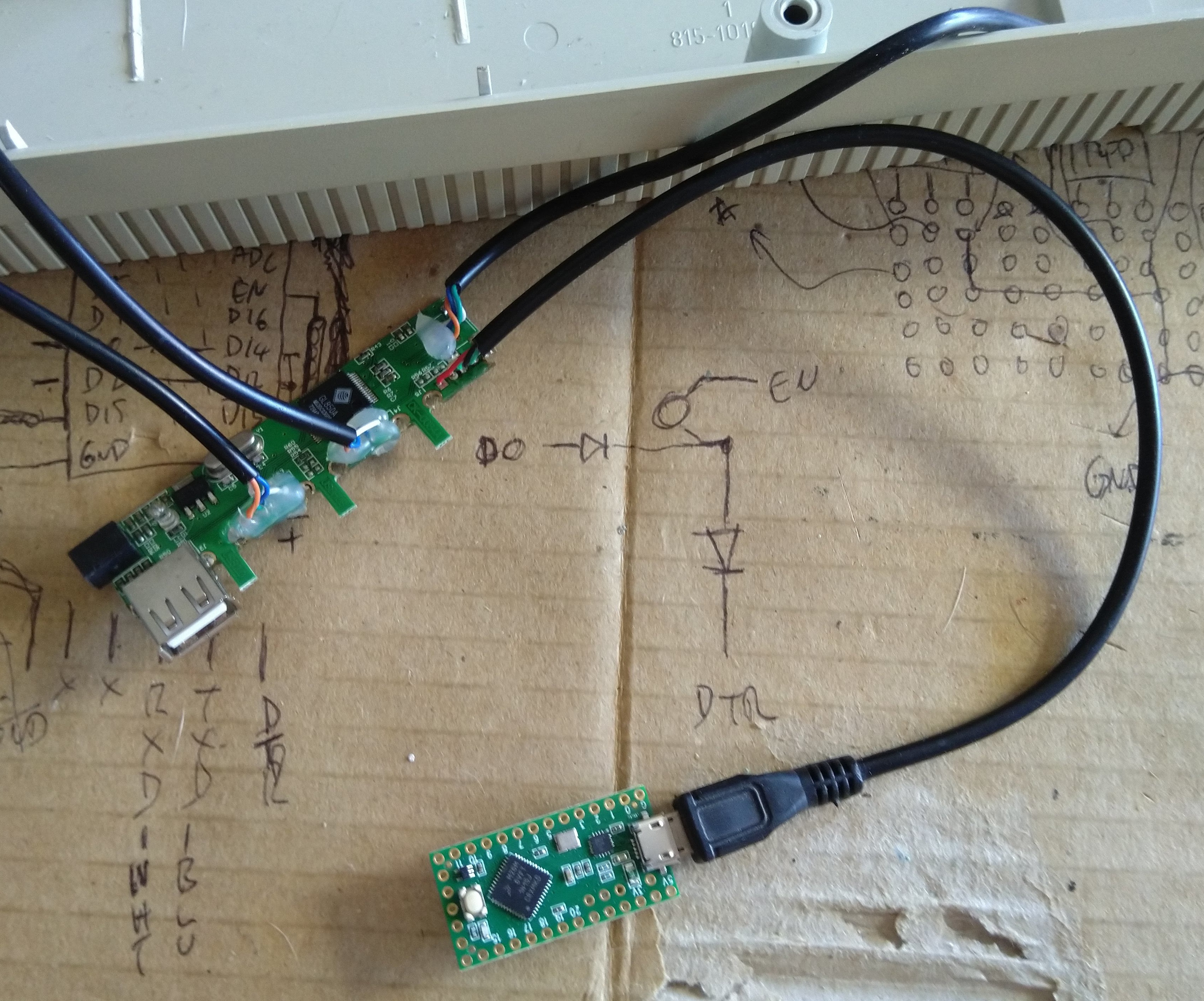
The original keyboard had a built-in USB 2.0 hub to drive the two USB ports on the right of the keyboard, I kept that, but replaced the hard-wired connection to the original controller board with a short USB micro-B cable. The idea here was that I could then glue the hub into the base of the keyboard's case and be able to disconnect the keyboard when disassembling. I ended up glueing the plug to the keyboard with hot glue during final assembly, so it's possible but not likely that I'll be doing that - the micro-B plug there is particularly cheap and doesn't hold onto the socket particularly well.
LEDs
I'd chosen the pins used on the Teensy LC such that the columns were all in order and on a single bank of pins in the hope that this would allow QMK to do something optimal - I don't believe it does - and forgot to check the current ratings of the column pins when I wired them up. Consequently I ended up with 4 pins left over: 13 which has the LED hooked up to it - which I wanted to leave alone - and 24, 25 and 26, which are really the "extra" pins which really should get used for other stuff and frustratingly all have 5mA current limits.
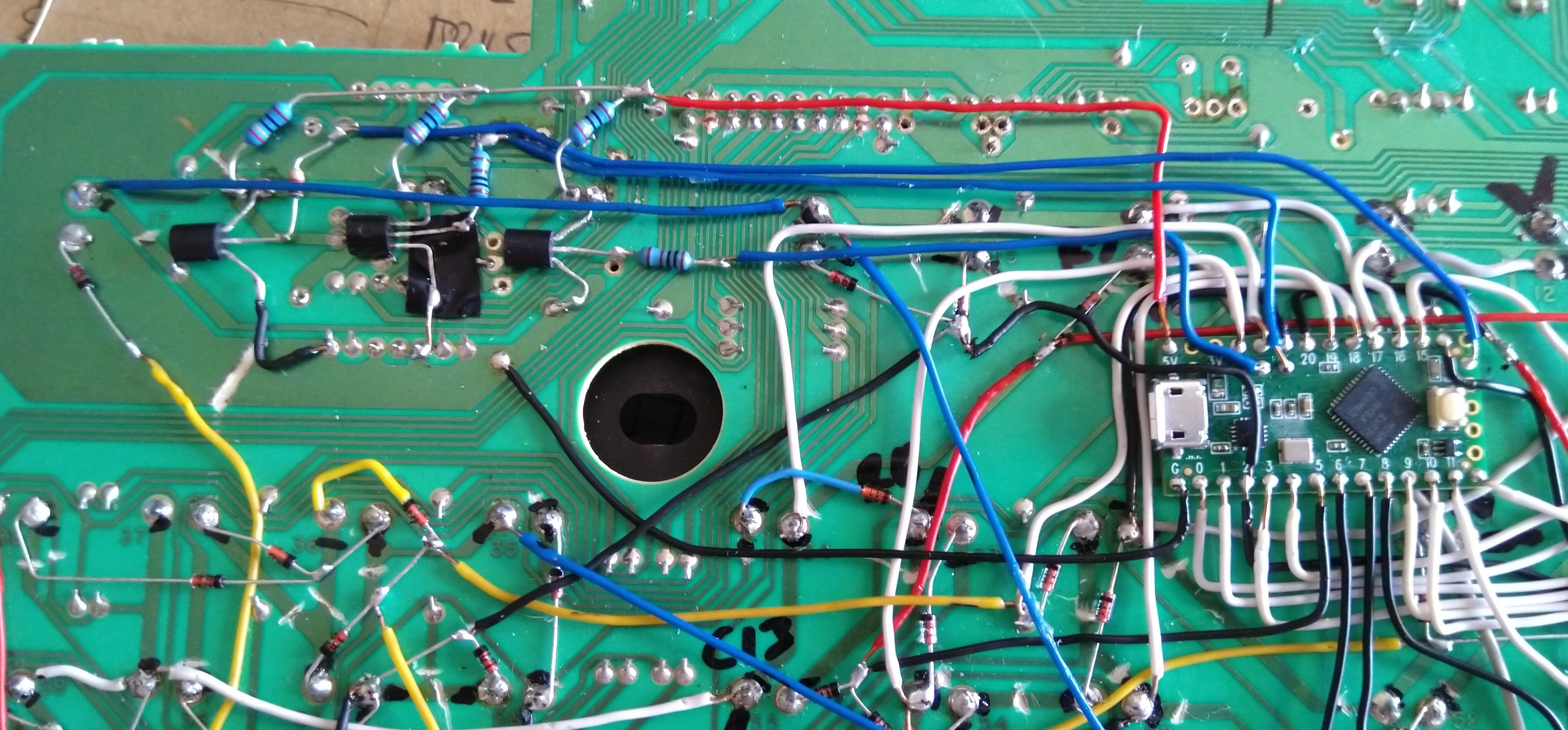
I therefore made the decision to use some of the huge stack of BC547s I had lying around to allow for a higher amount of current on the LEDs. One of the problems with the original keyboard was that the very old LEDs on the AEK weren't particularly bright when driven by the original USB controller board, so the mistake I made - using 5mA limited pins - ultimately gave me an opportunity to fix another minor problem with the original board.
The circuit here is pretty trivial: a 240 ohm resistor between the LED and +5v, and a 1K resistor between the base and the IO pin on the Teensy.
Those who know AEKs well will notice that the LEDs are hooked up backwards. When I was labelling the LED pins while removing the original controller, I incorrectly assumed that the common pin was negative and then designed my structure above with the LEDs backwards. When testing I quickly found that the LEDs weren't working, so I removed them and reversed them.
Final Touches
Once the entire thing was tested, working and all the keyboard wiring was finalised, I added hot glue to every "free" joint on the board:
- The transistors and connections around them.
- Any place where diodes met in a location away from an existing pad, e.g immediately to the right of the USB connector.
- Any place where a wire joined onto a diode's leg instead of onto a pad, e.g. where the yellow wire connects to the diode at the bottom left under the middle transistor.
As discussed, the USB connection to the Teensy LC was marginal at best, so a blob of hot glue was added to keep the USB plug from falling out (it was approximately where the blue and red wires cross)
I also firmly glued the hub to the bottom case of the keyboard, positioned so the remaining USB socket faced into the body of the keyboard. I've thought seriously about adding a Logitech Unifying dongle to that socket, but I primarily use this keyboard with a Bluetooth mouse, so it would be of limited use.
Despite all the modifications I made to the lower case of the keyboard when originally modifying the keyboard, the new location of the cable pressed against one of the remaining stiffening ribs, so that had to be modified to allow it space to move around the post that goes in the hole to the left of the connector.
At this point the hardware was complete: I could close it up, flash it with QMK and be done.
However actually getting QMK working here required a surprising about of effort, so I'll cover that in a separate post.
Discussions
Become a Hackaday.io Member
Create an account to leave a comment. Already have an account? Log In.