Close
0%
0%

NEURODRIVE

Muscle electrical stimulator for force feedback in Virtual Reality

Public Chat
Similar projects worth following
Hi! You are looking at neurointerface project for force feedback in Virtual Reality. I use esp32 and OSC protocol to generate real life sensations. So it is a real neurointerface :) because it stimulates muscles via nerves!
And if you don't need VR it can be a great device for experiments in muscle stimulation area.

This project on proof of concept stage now. I can grab virtual boxes with LeapMotion and make LED on the board glow with certain color.

I make streams on sundays with process of developing, but they are not too exiting :)))   

You can see how it works now. Interesting part starts from 18:30 

JPEG Image - 54.39 kB - 06/18/2021 at 09:19

Preview
Download

JPEG Image - 83.95 kB - 06/18/2021 at 09:19

Preview
Download

JPEG Image - 80.50 kB - 06/18/2021 at 09:19

Preview
Download

  • 1 × ESP32 MCU
  • 1 × ST7789 Display

  • The schematic and PCB now on easyeda.

    deluxe8705/04/2022 at 14:25 0 comments

    It's in development stage now. https://oshwlab.com/deluxe87d/neurodrive

  • Turning on

    deluxe8710/04/2021 at 23:18 0 comments

    Finally I made a first power up and actual muscle check. And surprisingly it was successful. It's only 24 volts mode but still you can feel a little stimulation on your hand

  • easyEda schematic started

    deluxe8708/02/2021 at 16:02 0 comments

    I started to draw schematic and pcb in easyEDA.  Now it's almost empty, but i hove it will be completely full of data in a few weeks.  So here is the link to the project  https://oshwlab.com/deluxe87d/neurodrive

  • High voltage pcb update

    deluxe8707/16/2021 at 10:35 0 comments

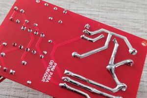
    I almost finished second PCB with H bridge, and high voltage converter, you can see it on the photo. I use chinese accumulator board in my design. I hope I will finish it in couple of weeks. See ya! 

  • Update summer 2021

    deluxe8706/18/2021 at 09:26 0 comments

    UPD: summer 2021. 

    So now it works more or less. I figured it out how to get a proper PWM signal out of ESP32. There was a mistake on last post where I wanted to use a complement PWM. The algorytm is mush simpler, I just need one PWM channel and second simple polarity switch channel. 

    The high voltage and power pcb will be ready in couple of days, and after that I'll be ready to work on software part 

  • PWM difficulties

    deluxe8712/10/2020 at 12:12 0 comments

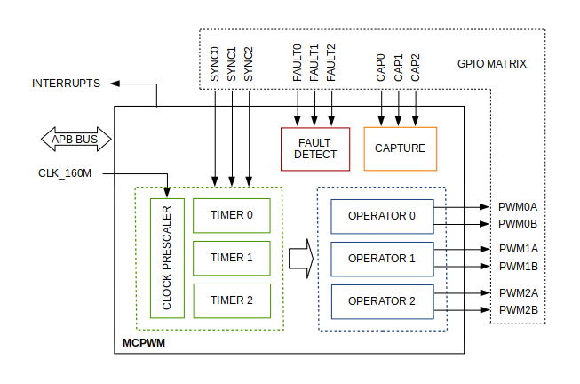
    Now I stuck with PWM generation on ESP32.  I need to generete a complementary or inverted PWM in order to drive H-bridge. I've already got that i need to use mcpwm module inside esp32, but i can't figure out what settings i should use. 

    As fa as i get it I should use 2 operators, for example operator - 0 and operator 1, and take one signal from PWM0A and another signal from PWM1A. Or maybe I'm wrong. Hope I will find it on this weekend.

View all 6 project logs

Enjoy this project?

Share

Discussions

Similar Projects

Does this project spark your interest?

Become a member to follow this project and never miss any updates