 Stefan Wagner
Features of the megaAVR
The ATmega4808 microcontrollers are part of the megaAVR 0-series, which uses the AVR processor with hardware multiplier running at up to 20 MHz from the internal calibrated oscillator. The series uses the latest technologies from Microchip with a flexible and low-power architecture, including Event System and SleepWalking, accurate analog features, and advanced peripherals. The following microcontrollers can be used with this development board:
| Controller | Flash | SRAM | EEPROM |
|---|---|---|---|
| ATmega808 | 8 KB | 1 KB | 256 B |
| ATmega1608 | 16 KB | 2 KB | 256 B |
| ATmega3208 | 32 KB | 4 KB | 256 B |
| ATmega4808 | 48 KB | 6 KB | 256 B |
All microcontrollers have the following features:
- 27 General purpose I/O
- One 16-bit Timer/Counter type A (TCA) with a dedicated period register and three compare channels
- Three 16-bit Timer/Counters type B (TCB) with input capture
- One 16-bit Real-Time Counter (RTC) running from an external crystal or an internal RC oscillator
- Three USARTs with fractional baud rate generator, auto-baud, and start-of-frame detection
- Master/slave Serial Peripheral Interface (SPI)
- Master/slave TWI (I²C) with dual address match,
- can operate simultaneously as master and slave
- Standard mode (Sm, 100 kHz)
- Fast mode (Fm, 400 kHz)
- Fast mode plus (Fm+, 1 MHz)
- Event System for core independent and predictable inter-peripheral signaling
- Configurable Custom Logic (CCL) with up to four programmable Look-up Tables (LUT)
- One Analog Comparator (AC) with a scalable reference input
- One 10-bit 150 ksps Analog-to-Digital Converter (ADC) with 12 channels
- Five selectable internal voltage references: 0.55V, 1.1V, 1.5V, 2.5V, and 4.3V
- Watchdog Timer (WDT) with Window mode, with a separate on-chip oscillator
- External interrupt on all general purpose pins
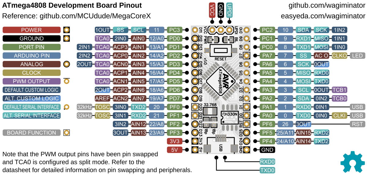
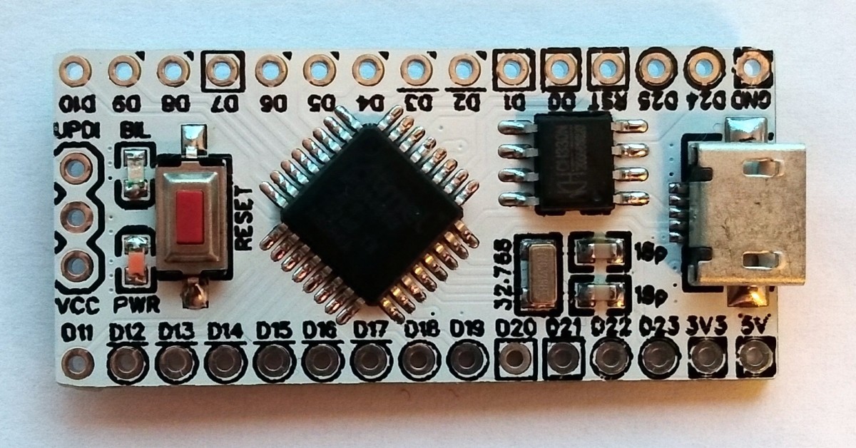
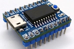
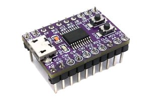
Pinout
Preparing Arduino IDE and Installing Bootloader
- Install MegaCoreX
- Open the Arduino IDE
- Go to "Tools" -> "Board" -> "MegaCoreX" -> "ATmega4808"
- Go to "Tools" and set the following board options:
- Clock: "Internal 20 MHz"
- Pinout: "32 pin standard"
- Reset pin: "Reset"
- Bootloader: "Optiboot (UART0 default pins)"
- Programmer: "jtag2updi(megaTinyCore)"
- Connect the UPDI programmer to the UPDI header on the development board. You can find such programmers in my projects or you can use an Arduino Uno as a UPDI programmer
- Go to "Tools" -> "Burn Bootloader"
- Disconnect the UPDI programmer and connect the development board via USB to your computer
- Open one of the attached example sketches and click the "Upload" button
Using the AVR DA/DB Family of Microcontrollers
The even more powerful AVR DA/DB family of microcontrollers (TQFP-32 package) can also be used with this board. Some of their features (depending on the model):
- Up to 128 KB of flash and 16 KB of SRAM
- Running at up to 24 MHz with internal oscillator (or even more with overclocking)
- 12-bit Differential Analog-to-Digital Converter (ADC) with 14 channels
- 10-bit Digital-to-Analog Converter (DAC)
- 3 Analog Comparators (AC)
- 2 independent OpAmps with integrated feedback resistor network
- Zero-Cross Detector (ZCD)
- Peripheral Touch Controller (PTC) with 22 self-capacitance and 121 mutual capacitance touch channels
- 4 Multi-Voltage I/O channels capable of bi-directional communication with external devices running at a higher or lower voltage than the MCU itself
- 3 UART, 2 SPI, 2 I2C
- 4 16-bit timers
- Configurable Custom Logic (CCL)
- Event System (EVSYS)
- Watchdog Timer (WDT) with Window Mode
In order to be able to use the AVR DA/DB microcontrollers with the Arduino IDE, DxCore must be installed.


 xukangmin
Aww you beat me to it. This looks great!