 Patrick Van Oosterwijck
I guess that one update was where the good news ended. *lol*
I found out today that the Pi 400 seems to have a 1A load switch on the 5V pins going to the GPIOs. Not that there's any good way to find out since I can't get hardware here and the Foundation still hasn't bothered to release schematics! Lately it's like they are actively working to try and make the life of third party developers such as myself difficult. They've never been the poster child of openness, but it's getting worse all the time. It's like they're trying to become Apple, making shiny consumer gadgets and have forgotten their original mission of providing a hackable product.
Anyway, if this is the case, the approach I'm taking here likely won't work. Not sure if anything would work really. It is possible that once the load switch is turned on, I can send power back to the Pi. But I don't know by what mechanism the load switch is turned on. Also, it's a 1A load switch so depending on how much other stuff is connected to the USBs etc, there may be more than 1A flowing through it once I'd start to power the Pi.
It pretty much means that "running the Pi 400 from a battery" is pretty much out. Working as a UPS may still be salvageable. Only testing will tell. This topology may need to morph back into the original "simple UPS for a normal RPi" if it doesn't work for the Pi 400. The Pi 400 may need a different approach, involving only the USB Type-C power input.
I also did some load testing on the G2263 boost converter. This is supposed to be a 9A switch current part, a "compact solution for a 5V output, 4A load requirement" according to the datasheet.
Well, in my testing it seems to be a whole lot less than that. I don't know what the limit is, but when I tested at 2A, the part got very hot (>150 °C, the maximum my FLIR can measure) and went into a hiccup mode (probably thermal protection kicked in to try to save the part from burning up). I tested it at 1.5A load and this is the thermal image for that:
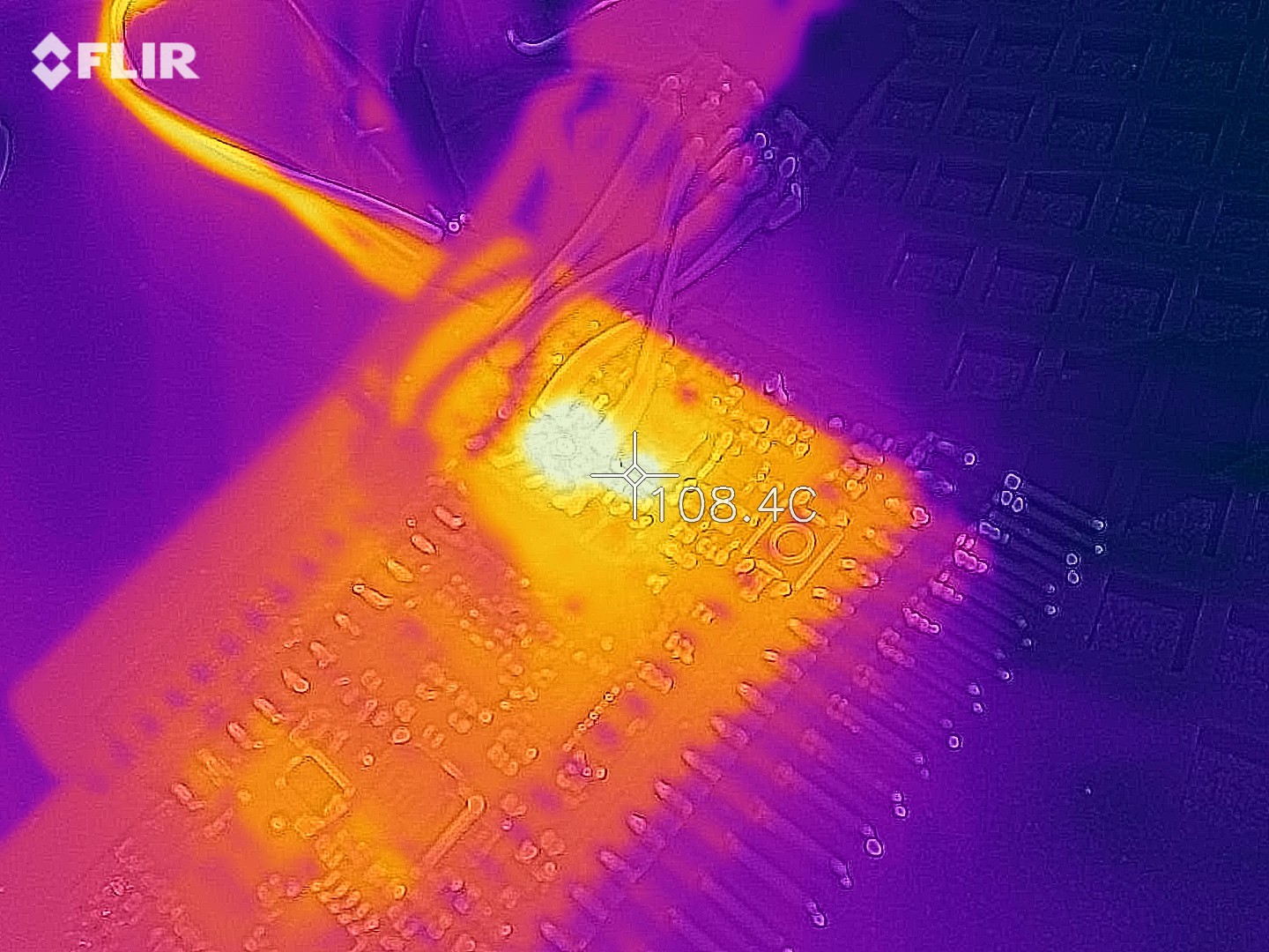
Still very hot but at least it seemed stable. This heat production is another indication that UPS duty may be a doable goal while running for long periods from the battery isn't really. The part can provide 1.5-2A for a short period of time, long enough for shutdown to complete.
I have also confirmed that the current sense amplifier seems to do its job (although the reading seemed a bit high, but that might just be due to trace resistance that isn't yet taken into account). It outputs a positive voltage versus a reference when power is produced from the battery and a negative voltage when the battery is charging. That should do the job for being able to detect whether external power is provided to the Pi or we are providing the power from the battery.
Discussions
Become a Hackaday.io Member
Create an account to leave a comment. Already have an account? Log In.
Is it possible that the inductor is just undersized for the current it's supposed to pass through?
Are you sure? yes | no