 Casey Banner
One of the central parts of the cockpit is the DED (Data Entry Display). Check out pictures of the real thing on xflight.de. Essentially, it's 256x64 display that displays 5 rows of text. It's used to navigate around various menus and displays relevant information based on what mode your in.
I'll cut to the chase and show a video of the final unit working:
I had this design built up on a breadboard, but I wanted a more permanent solution I could put in an enclosure, or on a panel eventually.
The first step was to design the schematic:
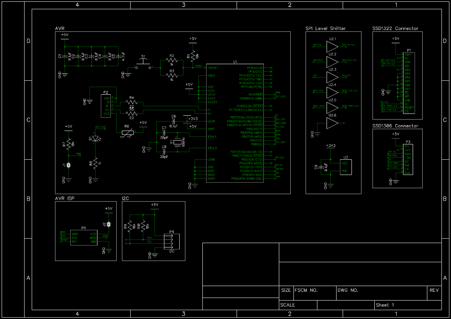
Essentially this is the support circuitry for an atmega32u4, USB connection, and connections to the displays. The 4050 is used as a 5v to 3.3v level shifter. In this design the communication with the displays is all one-way so only one direction is needed.
There are a couple of jumpers for configuration. J1 triggers the bootloader to run on reset, and J2 allows power to be supplied from the ISP programmer instead of USB. There is PTC between the USB power and the 5v rail of the board in case something goes wrong and draws too much current. I also included an I2C header, as my plan is to eventually have an ICP (explanation on xflight.de) panel with a switch matrix.
Next, I drew up a PCB layout. Since the atmega32u4 only comes in SMD packages, I did everything surface mount:
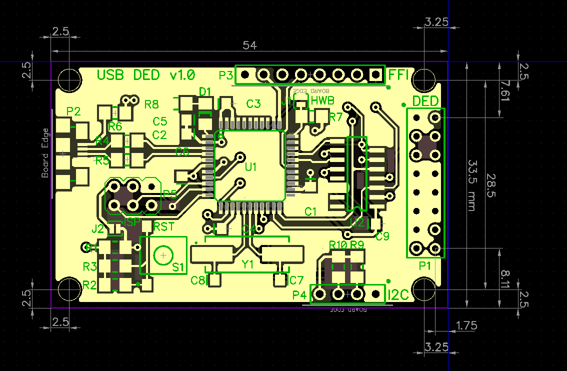
The dimensions are made to exactly fit the OLED module I am using. The board is a "backpack" that sits on the back of the board, connected via P1.
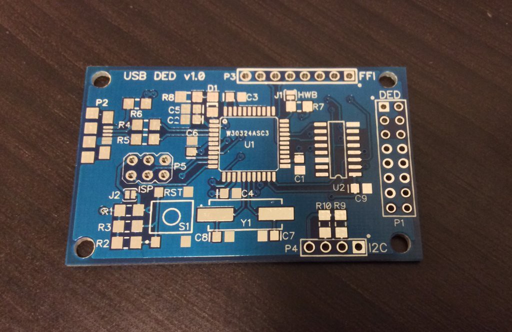
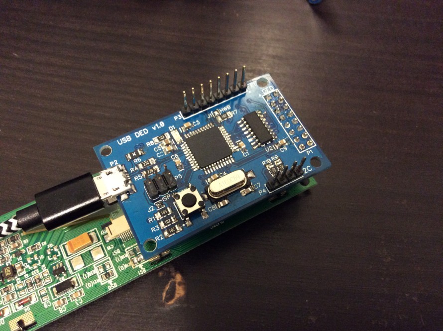
I sent the design to be manufactured by PCBWay, and it came out nicely:
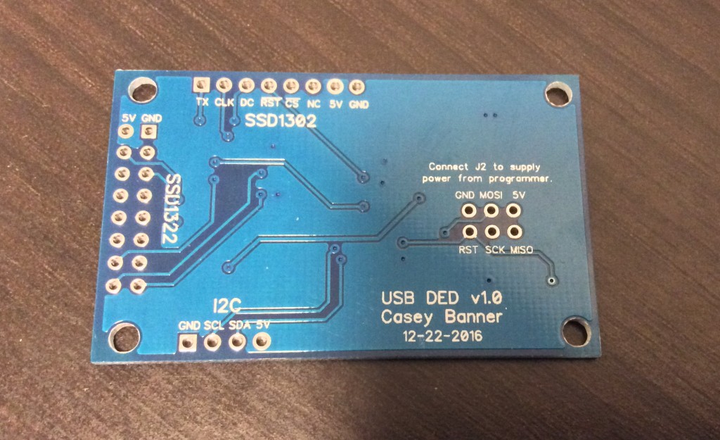
And the assembled board (hand assembling all the smd parts without paste or hot air was fun):
The firmware running at the atemga32u4 uses the LUFA library to present itself as a HID device. Display updates are sent via a windows application that sends 1bpp framebuffers (256x64 and 128x64) to the device. The micro then sends the framebuffers to the displays using SPI running at 8 Mbaud.
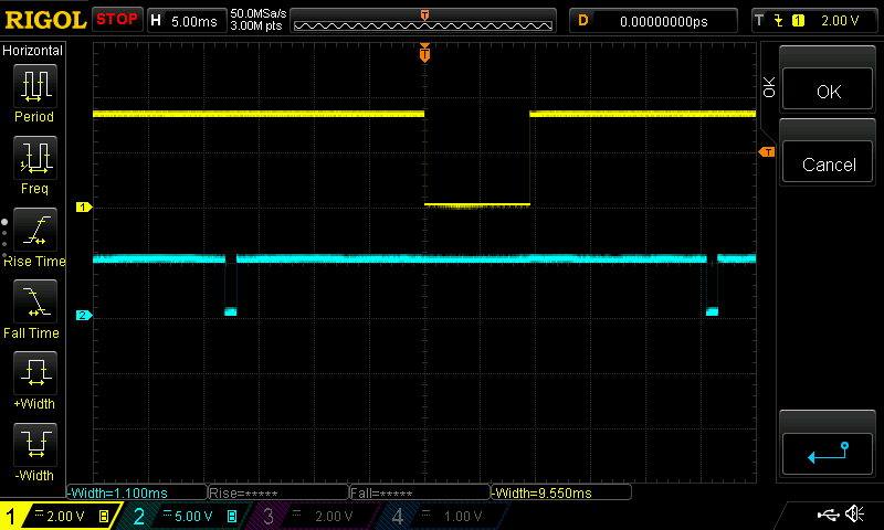
Here is a capture from the scope showing the two chip select lines. Yellow is the DED and blue is the FFI (fuel flow indicator, the smaller OLED seen in the video above). Because of the high speed, the update only takes 9.55ms + 1.1ms = 10.65ms total. If that total number is below 16.66ms, then I can send updates at 60fps, in sync with the game, with no stalls. I wasn't able to get this speed on the breadboarded prototype, because I had used a simple voltage divider as a level shifter, and the rise times were much too slow.
I'm super happy with how this project turned out! The next step is to design the enclosure, and start prototyping the ICP circuitry and I2C interface.
Discussions
Become a Hackaday.io Member
Create an account to leave a comment. Already have an account? Log In.