 Marius Taciuc
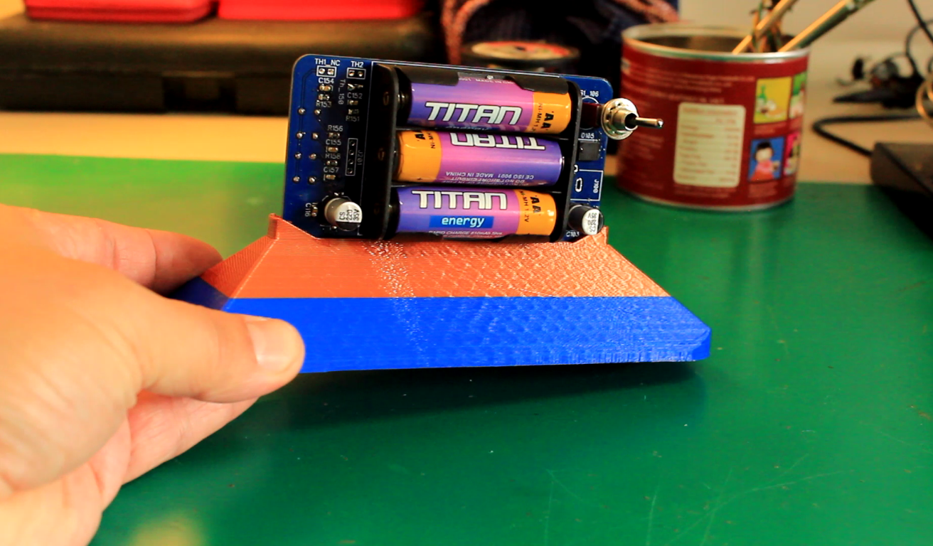
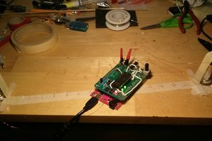
The stand support in the picture can be downloaded here:
https://cults3d.com/en/3d-model/tool/very-precise-thermometer-stand
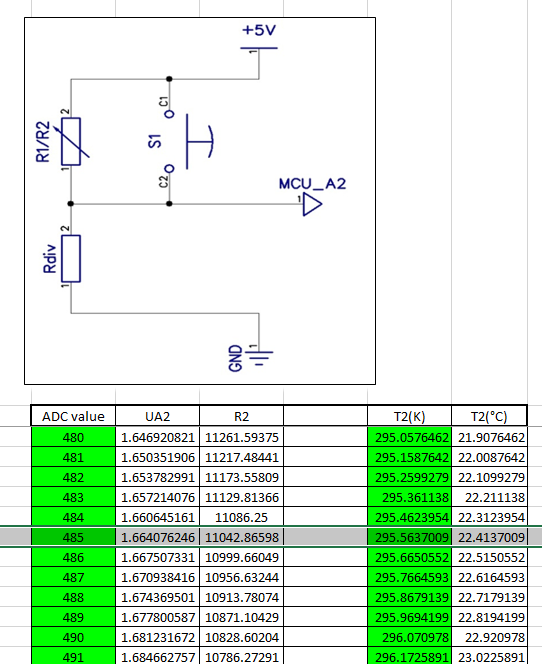
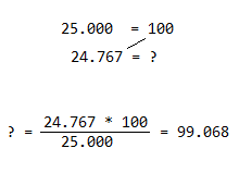
I've been playing with microcontrollers for many years now. In the years 2000, when I had to create a thermometer using ASM code, I was usually including a conversion chart in the software. Meaning that for every read value returned by the ADC, I was assigning a temperature value. I was always including the external thermistor into a voltage divider and I was reading a proportional voltage on the input pin. This software returned value had to be something between 0 and 1023. If, for instance, I was reading a value of 485, the PC registry of my microcontroller was going into the chart at the respective line and it was returning the temperature value of 22.41 Celsius.
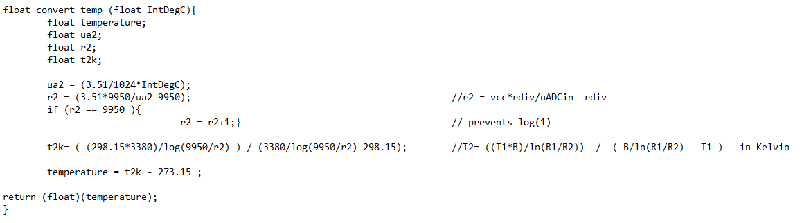
This was a very meticulous job and since I was also using some old thermistors with no datasheet, I sometimes had to sample the values of the thermistor myself and to create the sw conversion chart by hand. After a few years when the technology evolved and the C++ microcontrollers started to be very cheap and available to the masses, I realized for the first time that I can embed the transfer function of the thermistor into the software of the device. This is not only saving me the time to calculate and create the conversion chart by hand, but it can also calculate floating point results with an astonishing precision and a very large number of decimals.
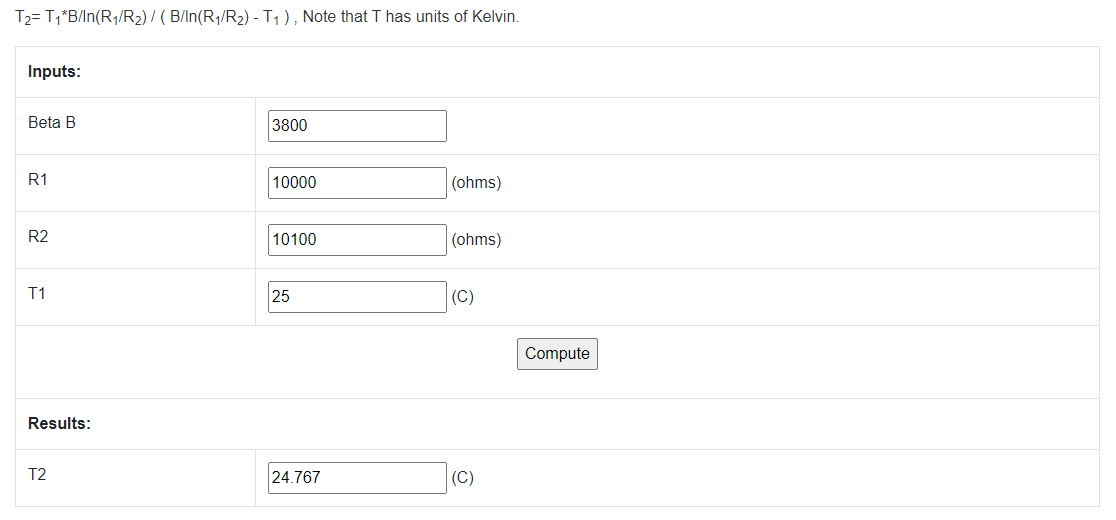
I then inserted the Steinhart & Hart Equation into the code and once I had the transfer function there, magic started to happen. For the first time in my life I was able to apply in a real manner all the things I have once learned about transfer functions during Special Math classes. I realized back then, the Electrical Engineering world would have never been the same without this scientific chapter. At least for me.
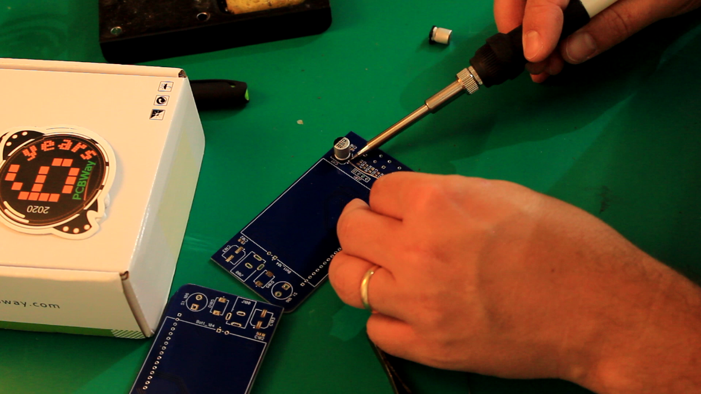
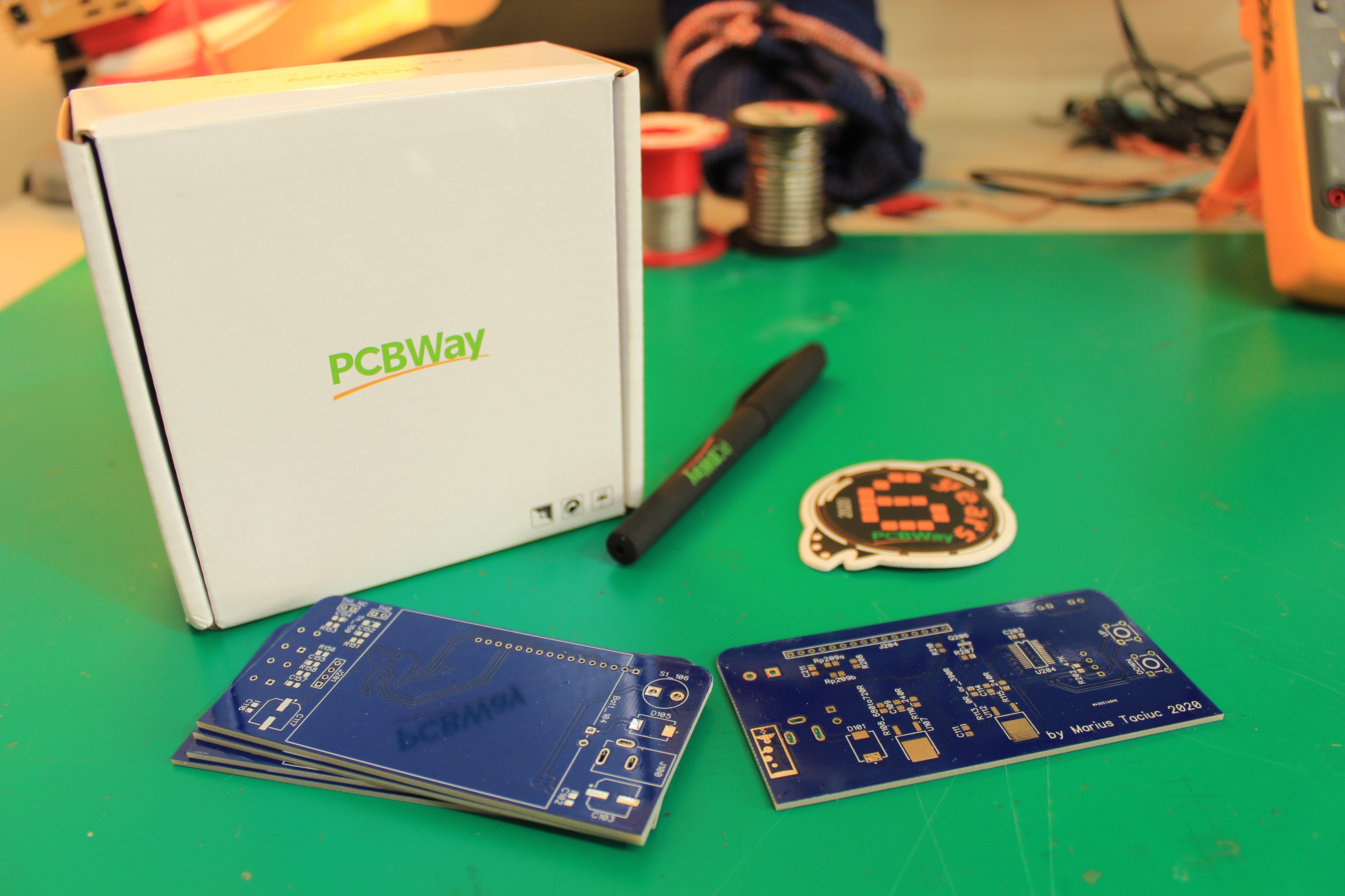
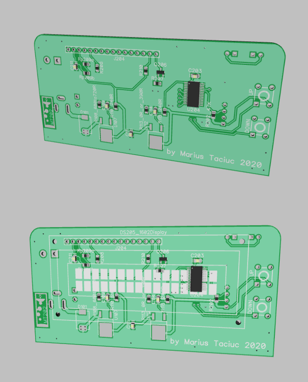
Once I received the PCB's I assembled everything by hand.
The official sponsor of this project is PCBway.com . For ordering your copy of these PCBs today, please follow the quick side link or visit the Instructions section for more details.


 Thatcher Chamberlin
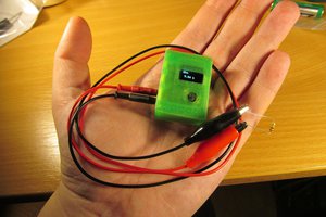
 jaromir.sukuba
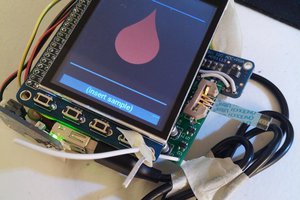
 Jonathan Buchanan
 Sebastian
very nice! I once had to use an NTC and didn't know about Steinhart Hart. After some research I found this page. which has a graph explaining where the Steinhart hart function is all about.
https://www.thinksrs.com/downloads/programs/Therm%20Calc/NTCCalibrator/NTCcalculator.htm