Summary of Intentions
I have an equatorial mount (Bresser Exos-2 which is similar to EQ5 ) without any tracker or GOTO device. I enjoy looking for celestial objects by myself.
But handling the telescope becomes a bit hard on my back after several hours of stargazing on a freezing night. I would like to add a remote control to allow the telescope to be controlled in more comfortable body positions.
It would be a DIY version of these commercial solutions:
- https://www.teleskop-express.de/shop/product_info.php?products_id=12424#cs
- https://www.bresser.de/es/Astronom-a-bresser/Accesorios/Motores-Mandos/BRESSER-Messier-RA-DEC-Motor-Regulador-Exos-2-MON2.html
I would like to emphasize that I do not intend to do a GOTO, just put two engines to move the OTA remotely. In addition, we will add the possibility that once a celestial object is found, the telescope follows it without the need for user action.
If you are looking for a GOTO project, I recommend these (they are excellent jobs):
- aGotino: https://www.cloudynights.com/topic/735800-agotino-a-simple-arduino-nano-goto/
- rduinoScope: https://hackaday.io/project/21024-rduinoscope-boianahttps://hackaday.io/project/21024-rduinoscope-boiana
Here it is presumed you are familiar with stargazing using telescope with equatorial mount.
Functionalty
- Move the OTA in both dimentions of the celestial spehere
- Vaiable speed by joystick
- Tracking a celestial object in three speeds: sidereal,solar or lunar
- Overheating, overcurrent alarm.
Requirements
Power Requirements
If you have an observatory, I envy you. The usual thing is to use the telescope in the field, far away from any power outlets and therefore a battery is need. Reducing power consumption to extend the life of the battery charge is an essential requirement in this project. For it:
- Since the speed requirement is not important in this case, we will use CMOS technology instead of TTL.
- We will try to reduce the current throw the resistors (in pullups, pulldowns, voltage divider, etc.) to the minimum increasing their resistances to the maximum.
- We will activate the “saving mode” (or “sleep mode”) in each of the ICs that have it. General speaking, we always chose the design alternative which implies less energy consumption.
Accuracy Requirements
When we action the joystick, we want the telescope moves in the correct direction and it is not necessary too much precision in the speed. We want the more the deflection the stick the faster the movement, and more near the central position slower motion must be produced. It does not matter if when the battery voltage falls the speed to become a little bit slower. Does not matter small changes in the speed produced by changes in the environment temperature neither. All these considerations apply when, I repeat, we are actioning the joystick, because we are not tracking any celestial object, we are only searching it, then no excessive precision is required.
But the thing changes in tracking mode. In this case we need the telescope follows the celestial object and keep it inside in the field of view as time as possible (it means always while it is visible). We must have in mind anybody could want this system for astrophotography. Therefore, for this mode it will be necessary to think in temperature compensation design. Although three screws will be provided for allowing the user to calibrate the system adjusting each tracking speed, the ideal thing would be that they must not be used for compensating external changes as temperature or falling voltage. We can accept the fine adjusts are used once or twice for year, maybe for compensating extreme differences of temperature between winter and summer or error given by the time equation. But after the system is calibrated, they should not be manipulated for a long time.
Why no Arduino?
That is good question and afraid I have not a good answer. Nowadays Arduino is a platform based in microcontroller which is present in a 90% of the hardware projects you can googling in internet. But I think this project is enough simple for not needing any hardware of general purpose based in software (microcontrollers, microprocessors, memories, etc.) I think we can achieve it using only basic and single electronic components and some typical ICs (timers, opamps, …) and basic logic gates.
On the other hand, I think if we design our control unit, we could reduce its consumption of energy chosen the proper components for it. I think a designed control unit for a specific functionality is (or it should be) more efficiency than another one programed of general purpose (Arduino DUE Microcontroller Board consumes about 500mA). Maybe I am wrong in this point?
I believe Arduino is good election for others more complex projects and I do not doubt, even, it could be a suitable solution for this one. I reserve that alternative for future extensions as, for example, to add setting circles which show us RA or Declinations coordinates or evolve the system to a GOTO device. For now, I would be satisfied with finishing this project, it will be util for learning about how to control an equatorial mount using stepper motors.
Why no Wii nunchuck?
I have at least two of them forgotten in some box. They have a very ergonomic design it is very comfortable hold them and use its joystick. But I have two reasons for deciding use a analog potentiometer joystick:
- Wii nunchuck is controlled by the I2C protocol, it would force to complicate the control unit for accepting this protocol. However, an analog joystick is two simple potentiometer and one interrupter, if you have any experience in analog electronic it will be easier design a unit control for it.
- I use the telescope with star charts which I put on a board. My intention is to attach the remote controller to that board, beside the star chart; the ergonomics of Wii nunchuck is not any advantage for me.
Why not PS2 Thumstick Joystick?
I seriously considered this possibility. In fact, I have made a prototype using a PS2 thumbstick and it worked, but it does not convinced to me (see logs).
System Parts

As you can see in the above picture, the final result will have three modules:
1. A Remote Control which is wired to the Unit Control. It will have the interface with the user. In it you will be able to:
- Choose the mode:
- Manual mode: the mount will be moved according to joystick action with variable speed. In this mode if the joystick is not acctionated, the mount reamain motionless.
- Tracking mode:
- In tracking mode without joystick action, only the the RA motor will be moved with the selected tracking speed: sidereal, solar either lunar.
- On the other hand, in tracking mode, if joystick is actioned, it will respond as the manual mode until the joystick is released. After the joystick has been released will continue the tracking movement.
2. A Unit Control which controls the system. It recive the commands from the remote control and act on the stepper motors. It will have be three small screws what let us to correct any possible maladjustment in any of tracking speed. It only will be necessary use them occasionally for calibrating operations.
3. Two stepper motors.
Why Separate the Remote Control from the Unit Control?
In most commercial solutions (in fact I believe all of them) the keys for control are attached to the control unit in a compact case.
We do not have as much integration capacity as the manufacturers and, therefore, our unit control will be larger, but if we are not going to hold it that does not matter to us.
On the other hand, I would like managge the system at the same time that star charts, the smaller controller the best for me. In addition, I think that offering this solution will allow each one to design the control remote adapted to their needs and preferences. But feel free is you want to join the remote control and the unit control, I think it will imply only small changes to the design.
Two States
1. Normal state: The normal working state, no errors.
2.The Warning State is activated in the event that any of the fault signals are activated (due to overheating, overcurrent ...) in any of the drivers of the two motors. In this state, both motors are disabled and it will not be possible to operate, an acustic and optict alarm will be activated. It will only be possible to exit the Warning state by turning off and then on again.
Connections between the Parts
Lets see the connections between the parts of the system:

From the controler we can choose the mode (manual or tracking), this information is given to the Unit Control by Mode signal.
The signal Jacc informs the joystick is if acctioned or not. Does not matter the direction or amount, this signal is activated when you move the joystick.
X and Y analogical signals inform the amount of movememt of the stick, X for horizontal movements and Y for vertical ones.
Sx1, Sx2 and Sx4 give the multiplier factor of the velocity. With Sx1 motors rotate slow and it is used for searching a celestial object near the field of vision, however when Sx4 is activated the speed of motors is four times faster than Sx1; it will used for searching far targets. We cannot activate more than one of those signal at same time.
Vcc and Gnd are the supply voltage and the ground voltage respectively.
On the other side we have two stepper motors (one for RA and the other for Dec), each with two coils and each coil with two connectors.
The interior design of the remote will be very simple, just pullup or pulldown resistors to set the digital signal to a high or low level accordint to the position of the switches. It will have too the PS2 joystick which will give two analgical signals (X and Y) given by two potentiometers.
The complex of logical for controlling will be in the control unit.
A Little Spoolier
Maybe in this moment you are asking yourself how we can manage the speed motor using a joystick. The basic idea is the showed in the next figure (front to back):

A stepper motor is controlled by intensity, which go throw its windings, more intensity more speed. Fortunately exists ICs for this task, they are called “drivers”.
The driver is controlled by a signal of pulses. The higher the frequency of pulses signal the faster the motor moves.
For generating the signal of pulses, we can use a voltage-controlled oscillator (VCO). I am thinking in VCO based in a 555 timer. As you know, we can control the frequency of the output signal of this kind VCO with a Vcontrol voltage. But (here starts the difficulties), the relation between Vcontrol and the output frequency is not directly proportional. When Vcontrol is decreased, the output frequency is increased and vice versa.
In our case we need minimum speed when the joystick is the center position, that means maximum voltage in Vcontrol. That is, we need maximum voltage in central position of the joystick and minimum one in its extremes, it will be supplied by the transductor, which we must design.
The transductor will take as input the resistance of the potentiometers of the joystick (0 to 10 k Ohms) and will convert to voltage: minimum volts in the extremes and a maximum voltage when the joystick is the central position. That is, the form of the transfer function for our transductor (voltage vs resistence) will be a triangle.
And finally, at the begin of this chain, is the joystick, which has two potentiometers of 10k, one for X direction (RA movement) and the other one for the Y direction (Dec movement). In the rest position both potentiometers have a resistance value of 5 K Ohms.
Of course, the above said is only the main idea. We need more details I will give later. For example, as I have mentioned in the Accuracy Requirement section, we need extreme precision and therefore temperature compensation in tracking mode. But that only affect to the RA motor, not the Dec motor which will sleeping in that mode. Thus, the design for controlling RA will be a little different than the Dec. one.
Why not Use Directly the Potentiometer of the Joystick in the RC Circuit of the VCO?
As everyone know, the frequency in a 555-VCO can be modify changing the value of the resistor in one of its two RC circuits (the one for charging or the one for discharging). Then the first idea which arrive to our mind is make the variable resistor of the joystick belong to the resistance of the charging (or discharging) circuit (see Fig. 4. A).
That appears to be direct and simple, but when we start to develop it, we will find some difficulties. The first one is we need minimum frequency at the output of the VCO when the joystick is in the center position, that is when potentiometer is at the middle of its range. Unfortunately, if we connect the potentiometer as is shown at Fig. 4a (in a “classical form”), we will have not the desired behavior:
We need maximum resistance (or minimum) in the center position and the minimum (or maximum) resistance in both extreme positions. Further, the resistances in the extreme positions (max. or min.) must be approximately equals since it would involve the same speeds for the forward movement as for the reverse movement. No of these conditions are satisfied in the circuit Fig. 4. A, but they are met in the one of see Fig. 4. B, where we have shortcircuit both endings of the potentiometer.

Well, now it looks good. As we wished, positions Xmax and -Xmax have the same resistance (ideally 0 ohms) In fact, range from 0 to Xmax is indistinguishable from its specular range from 0 to -Xmax, and it here is, precisely, the problem: we need not only know the magnitude of the offset from the center position, we need know too the direction of that offset (north or south, east or west), for this reason, unfortunately, the second circuit is not a suitable alternative for our purposes either.
As conclusion, we cannot use the resistance of the potentiometer of the joystick to control the R in the RC circuit. For the same reason we cannot use the potentiometer of joystick as voltage divider and obtain the voltage control for the VCO.
Experimenting with the Mount
We are going to start from the end towards the begin in the Fig. 3, we start to ask us about what angular speed should rotate the motor, then what frequency is necessary at the input of the driver for obtaining that angular speed and at last what is the voltage necessary at input of VCO for obtaining that frequency. Later, in other phase we will design the transductor for obtaining the voltage range necesary from the resistence of the potentiometers of the joystick, but it well be later.
To answer the first question you must experiment with your mount. The mine one is a Bresser Exos 2 mount, but I am pretty sure it is like (where I have said “like” I wanted to say “equals”) others eq5 mounts in the market. In fact, I believe they are made by the same maker (maybe in some place in China) and then put on them the label for the vendor (Skywatcher, Bresser, etc). The following characteristics are from my own mount, but I suspect they do not differ too much for yours (if it is an eq5 too). If that is not the case, you will need to take the specific characteristics from you mount doing as I will describe.
Since the motor will be coupled to the RA (and the Dec) fine manual driver we need to know the relationship between the manual drive and the movement of the OTA. In other words, if I rotate a degree the manual drive how many celestial degrees move the OTA?
To find out this information, I rotated both knobs a certain number of turns and observed the result in their setting circles. As result I obtained the following relations:
- Six rotations of RA manual drive implies the OTA turns one hour to east (or west) that is it moves 15 degrees in the celestial sphere.
- Two rotations of the Declination manual drive implies the OTA moves five grades to north (or south).
| RA ratio | 6 rotations / Hour (15 celestials degrees) |
| Declination ratio | 2/5 rotations / degree |
I insist, you must check these relationships in your own mount; they are the basis for the following calculus.
From now we will pay attention only the RA movement since it is the only one which is concerned for the tracking speeds.
If six rotations move the OTA fifteen degrees then how many degrees in the RA driver are need for the OTA move only one degrees?
Having 1 rotation is 360 degrees then six rotation are 360x6 = 2160 degrees, and they move fiftteen degrees. So to move the OTA an only degree will be need 2160/15 = 144 degrees in the RA drive. That is an important conclusion:
| To move the OTA one degree we need rotate the fine RA drive 144 degrees |
(As I said, note that this conclusion may not be true for your mount.)

In other words, for RA drive our mount can be seem as a reduced speed motor with a 144:1 ratio; or what is the same thanks to the mount we must multiply the angular speed of the motor by 144. That is good for us, because the sky moves very slowly. Further, as we will see later, we must add gears between the motor and the RA drive that are going to increase this ratio even more.
Transmiting the Movement from the Motor to the Mount
We have two posibilites:
1. We could use gears in contact (see Fig. 6A). At the motor shaft will be the drives one with a minor radio and at RA drive will be the drived one which will be the largest. This is the comertial solution I have always seen, but I see a problem for making by ourself: we will need two gears with exact distancies between the shaft. Do you know where we can get them?
 B. Transmiting movement by pulleys and timing belt (Scrapped too!).")
2. We could use two pulleys and a timing belt (see Fig. 6B). The problem here is that we will need to keep the strap taut, we could use an extra idler pulley for that. Do you know where we can get it? I thinking in this:
I have found many driver and driven pulleys on the internet that could be useful to us, but I have not found an idler pulley with the spring tensioner and attached to an arm as shown in the figure. I talking about small pulleys (for belts with a width of 6mm approx.). for larger ones (eg car engines) we can of course find them, but they are not useful for our purpose.
We will chose option B but without idler pulley. We will keep the belt taut using loose holes to fix the motor. These will allow us to bring both axes closer when we want to loosen the belt to remove or put it on and move them away when we want to tension it.
Choosing the Components for the Transmission Mechanism
For developing the mechanism showed in the Fig. 6B we need first to meseaure the diameters of the RA drive shaft and the motor shaft. This will determ the bore diameter of each pulley.
I have used a caliper for taking the these measurents and in my case are:
| RA drive shaft | Form "D". 6mm |
| Motor shaft | I have not bought yet, but in its specifications I read: Form "D". 5 mm |
Googling I have seen the following components are frecuently used for 3D printers:
Driver pulley
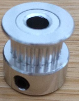 | Teeth: 20 Bore: 5 mm |
Driven pulley
 | Teeth: 60 Bore: 6 mm |
| Timing belt | Wide: 6 mm I am waiting for the drive pulleys and the motor. When I have them I will be able to measure the necesary length for the belt. |
Engine Speed Reduction
If we use the components mentioned in the table above, we will have a ratio between the driving pulley and the driven pulley equal to 1: 3. It means that the power transmission mechanism in Fig. 6B will be equivalent to a motor speed reducer in 3. And if we also take into account that the mount (in the RA axis) also reduces the speed 1: 144 (see Fig. 5), then the set behaves like a 1: 432 reducer.
To sum up:
| To move the OTA one degree in RA the motor have to rotate 432 degrees |
We will must keep in mind this when we will calculate the speeds of motor.
We are lucky because 432 is a good number for our purposes. Why I saying that?
On the one hand 432 is something 6 times and we measure the time (and therefore RA) in multiples of 6.
On the other hand, we can divide 432 by 16, by 4, and of course by 1; and if you take a look to the remote control in Fig. 2 that is just we need.
The Motors
")
We will use two type Nema 17 stepper motors with a torque 45N.cm
Why this torque? In fact, I do not know what the proper holding torque is. The mount acts as a retainer on its own, so not too much holding torque is required from the motor. The higher the torque of a motor, the heavier it is, and we should add as little weight as possible to the mount. I think 45 Newton x cm is enough.
I have ordered a double shaft motor. The double axis does not contribute anything to this project, I have only done it thinking in the future to add a decoder.
Understanding the Stepper Motors and the Drivers for them
To continue we need have minimum knowledge about the stepper motors, if you have it (probably more than me) you can jump this section.
As their name’s suggest, a stepper motor moves step by step, that is a discretional number of degrees. A Nema 17 moves forward (or backward) 1,8 degrees each step. Does that mean they cannot move smoothy? No, it does not mean that, they can do it if a step ends when star the following one. But it does mean we cannot stop them in intermediate position? No, it does not mean that, we can. How?
A stepper motor is controlled by the intensity of the current that move through its windings, and the one we have chosen has two of them (for that reason they are named "bipolar"). If the current move through both winding at the same time the rotor moves at in intermediate position, a fraction of 1.8 degrees. The exact amount depends on the intensity of both currents.
Ummm…. Controlled by intensity, more than one windings, degree by steps, parts of steps, synchronizing steps, … it looks like too complicate! but it is not. Fortunately for us we do not have to worry about nor intensity neither windings, there are chips which do it for us: the drivers.
The drivers simplify our work since they accept pulses as entry and send current to the motor as output. One pulse, one step (or one microstep). Can it be easier?
We will use the driver DRV8825, an alternative would be AR988, but this last does not allow so much current as the first. Above I have mentioned “microsteps”, what are they? They are a fraction of a step. The DRV8825 driver allows us divided a full step until 32 microsteps (we can configurated for dividing by 2, 4, 8, 16 and 32).
The advantage working with microsteps is we will obtain smoother movement than using full steps. The disadvantages are we will obtain less retention torque and exists the risk to jump some microstep. We can assume these disadvantages; the mount retains the OTA enough and we are not designing a GOTO positioner therefore the jumps are not so much important.
For now, we decided use microsteps (divided by 32) for the tracking speed, which is the mode where we need more smoothly.
Calculating the Frequency for the Tracking Speed
To do so we will use two previous considerations that have already been seen:
- The ratio between the angular speed of the motor and the movement of the OTA is 432. That is, for each 432 degrees in motor the OTA moves one degree in the sky.
- We will configurate the driver in 32 microsteps. It means for reaching a full step (1,8 degrees) we will need to provide 32 pulses.
Keeping in mind these both considerations:
- Amount of RA drive degrees for completing an RA hour will be 435x15 = 6480 degrees. I remember you 1 RA hour are fifteen degrees.
- Complete steps required to complete one hour of RA: 6480 / 1.8 = 3600 full steps. Oh! That is a round number!
- Number of 32 microsteps needed for completing an RA hour: 3600 x 32 = 115200 microsteps.
- And finally, frequency for sun tracking: 115200/3600 = 32 pulses/seconds. Note one hour is 3600 seconds.
Then we can conclude:
| The necessary frequency for solar tracking is 32 pulses/second. |
Time and Times
32 pulses by second sounds pretty.
But if you have something of Astronomy inside of your mind, maybe now you are asking what kind of seconds they are? Obviously, in electronic we must work using “clock time” that is “mean solar time”.
As you know, the real sun is not a mean sun. In winter it moves faster and in summer it moves slower. For correcting it we would have to add to our design something to compensate that the Earth does not move constantly around the sun; we would need introduce the equation of time. But I have thought it would complicate our project too much. Do you think I should do it?
As a consequence, our system will only follow the Sun perfectly in January, April, June, September and December. The maximum error will be at the beginning of November, which will be anticipated, but not with an error of no more than 16 min. per day, which I think is manageable.
A Celestial Race
Let's talk about the anothers tracking speeds: Sidereal and Lunar.
At the sky, the sun, stars and the moon move in different speeds. For see it let's see a celestial race:
In more than 20 years from now (on August 23, 2044) there will be a solar eclipse that can be seen from Madrid.
That day the sun, the moon and the star Regulus (in the Leo constelation) will be at the same point in the sky. We can see it at the Fig. 8a.

At the Fig. 8b you can see that the next day (exactly 24 hours later) they will no longer be together: Regulus will be in front of the group followed by the Sun about 4 minutes and behind all of them (the slowest) the moon, delayed 72 minutes with respect to the Sun . Of course, they are all apparent speeds from our point of view as an observer on Earth.
Conclusion:
The stars are the ones that move the fastest. They go ahead of the Sun about 4 minutes a day.
The Moon is the one that moves more slowly; it delays its rise a little more than three-quarters with respect to the Sun.
"Respect to the Sun" Why I am always talking "respect to the Sun"? Because the human mesaure the time respect to the sun. For us 24 hours is the time the Sun (no the stars) takes return to the same position which it was the last day. Our clocks mesure solar time, not sidereal time.
Designing the VCO
Now we know the frecuency for sun tracking speed is 32Hz we will be able to design the VCO of Fig. 3.
We must also take into account that we want stability against the loss of battery charge. Let's say we admit a voltage drop of 2 volts that is up to 10 volts. To make sure we will place a voltage regulator between the VCO and the battery that ensures at least 9 V. The schema around the VCO we be the following:

At 6V in Vcontrol, the VCO will give the lowest frequency (32Hz) and the motor speed will be the slowest (the tracking speed). This will be when the joystick is in its center position. Getting 6V when the joystick is not actuated will be a task of the Control Circuit.
When the joystick is in an extreme position the control circuit will give 1 volt (How? We will see later). Then at the output of the VCO there will be almost 82 Hz and the motor will rotate at maximum speed. Why 82 Hz? Well, I must confess that I only designed the circuit so that with 6V in VControl we get 32Hz, then I put it in an electronic emulator and I saw what happens if we reduce Vcontrol to 1V. The result was 81.84 Hz.
Maybe seeing Fig. 9 you are asking why the driver is not under the voltage regulator. The answer is because is not necessary. The specs for DRV8825 say we can use a supply of 8.2volts to 45 volts. But there is a stronger reason. If the battery gives, for example, 12v and the regulator down to 9v there is a difference of 3 volts which produce an energy consumption. This consumption is proportional (in addition to the voltage difference) to the current. If we exclude the current that feeds the motor, we will save on this consumption.
Fig. 10 shows the VCO that I am proposing, of course it is not the only one possible. As you can see I am an original person: I have used a 555 timer for it.

You should note that the design in Fig. 10 is only a theoretical design (although I have already simulated it with Microcap and even mounted and tested it on a protoboard). In real VCO we will not use a 555 but a 556 since we need two VCOs (one for RA and one for Dec). Moreover, we will specifically use the CMOS version ICM7556 (or TS556), to reduce power consumption. Furthermore, we have to add the other two RC networks to the RA VCO to obtain the other two tracking frequencies: lunar and sidereal.
We must also bear in mind that commercially we will not get resistors (or capacitors) with the exact values calculated, so we have to add adjustment potentiometers to the circuit. These potentiometers will be useful, too, to compensate that the voltage regulator will not deliver exactly the required 9.00 Volts. Once the circuit is assembled, an oscilloscope (or frequency counter) will must be used to adjust the potentiometers.
Lastly, we should also add NTC resistors to compensate for temperature variations. You are going to help me with that, aren't you?
I have emulated the cicuit of Fig. 10 in microcap 12:

As you can see in Fig. 11, when Vcontrol = 6v we will obtain near 32Hz as output. And as you can see in Fig. 12, when we reduce Vcontrol to only 1v then we obtain near 80Hz:

I have upload the file for this emulation: VCO3.cir.
Let’s Start by the Basement
We have started the house by the roof; the VCO is one of the last stages. But we need think about the roof to build the rest of the house. We now know we will need a control voltage from 1 to 6 volts. And we know, also, we need 1 volt in both extreme positions of the joystick and 6 volts in the middle.
Knowing that, we can now think about the basement, the first stage: joystick to transductor:
