 Sebastian
Today I tested the circuit I constructed last week (previous log).
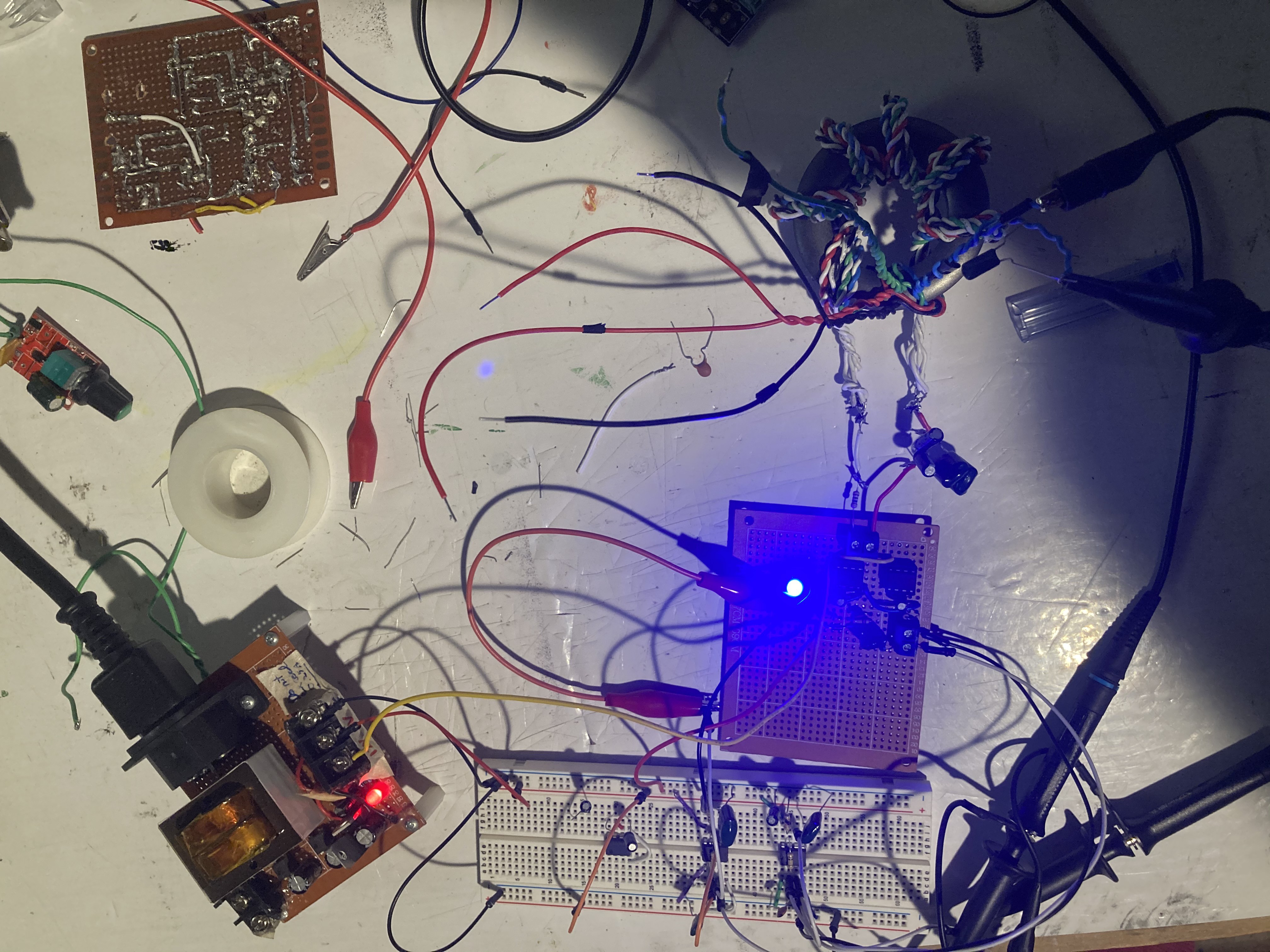
Changes made since the last log include: inserting the FET driver ICs into the control board and soldering a 10ohm resistor and a few capacitors to my Gate Drive Transformer (GDT).
For the signal inputs, I used two 555 circuits to produce two square waves--one of ~200KHz and the other 10Khz or so. The entire test was powered using the power supply from my SSTC v1 project.
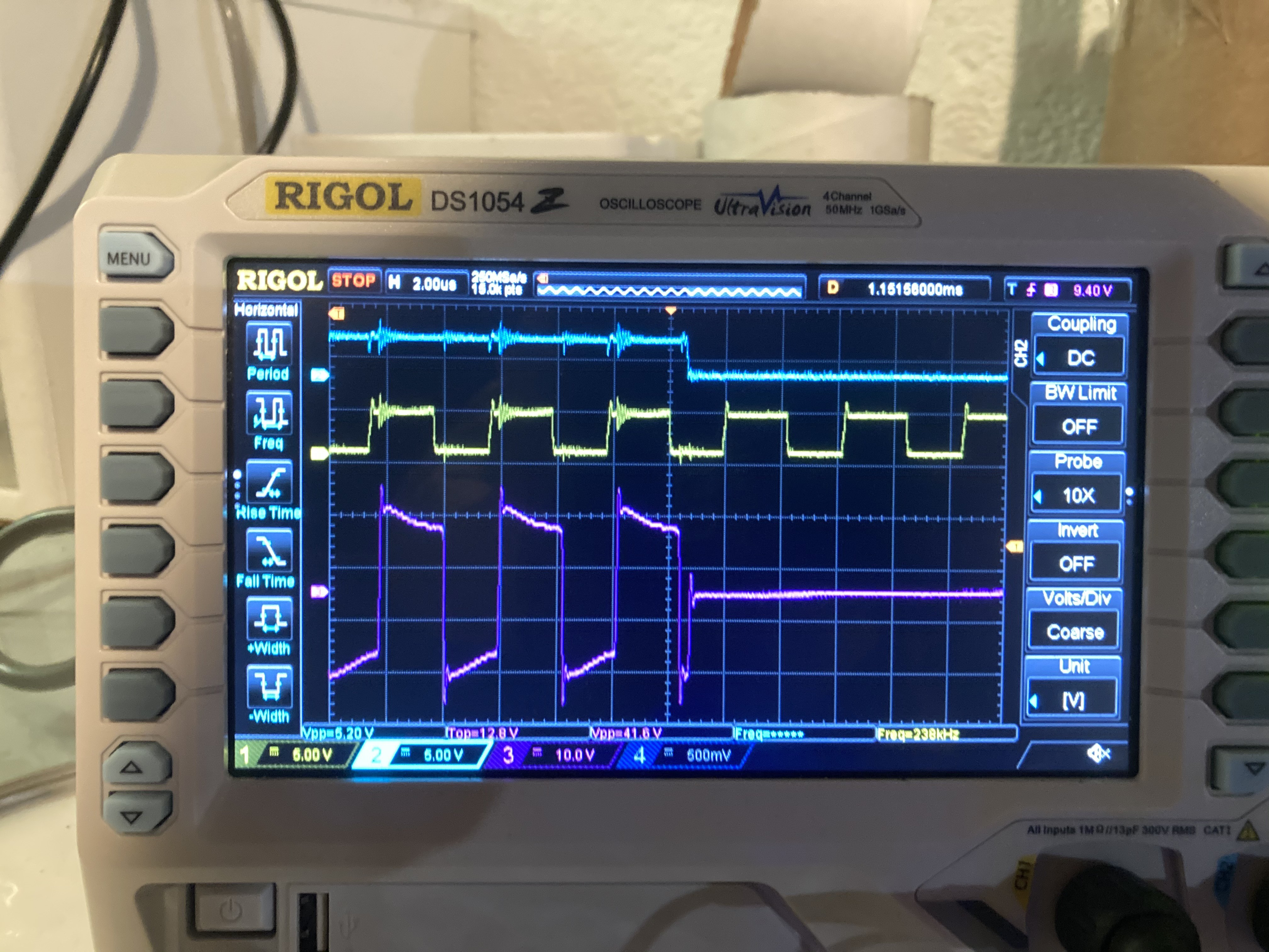
I was pleasantly surprised when the whole circuit worked upon powering it on. Upon connecting both inputs to the circuit, I measured a 40V peak-to-peak square wave on the output of one of the GDT's secondaries. The driver ICs had no problem with receiving the input signal without implementing Schmitt trigger hysteresis--though most designs for this type of circuit include an IC for this purpose, I decided to omit it for simplicity. In addition, with no feedback signal, I still measured an output (lower frequency) on the GDT from the interrupter signal which means that I can reliably power on the Tesla Coil and hopefully should not have to worry about the feedback system failing as an interrupter signal will be able to prime or "jump start" the oscillation process.
Photo documentation:
(Scope signals below: blue=interrupter, yellow=feedback, purple=a GDT secondary)
Discussions
Become a Hackaday.io Member
Create an account to leave a comment. Already have an account? Log In.