 zpekic
While overall the sampling of TIM-011 video signal works, and is visibly displayed on the screen, it still has problems:
- first column pixel is displayed (black instead) because there is no real pixel pipeline (and consequently, the last pixel column is not displayed
- there are some random "ghost artifacts" (vertical bars)
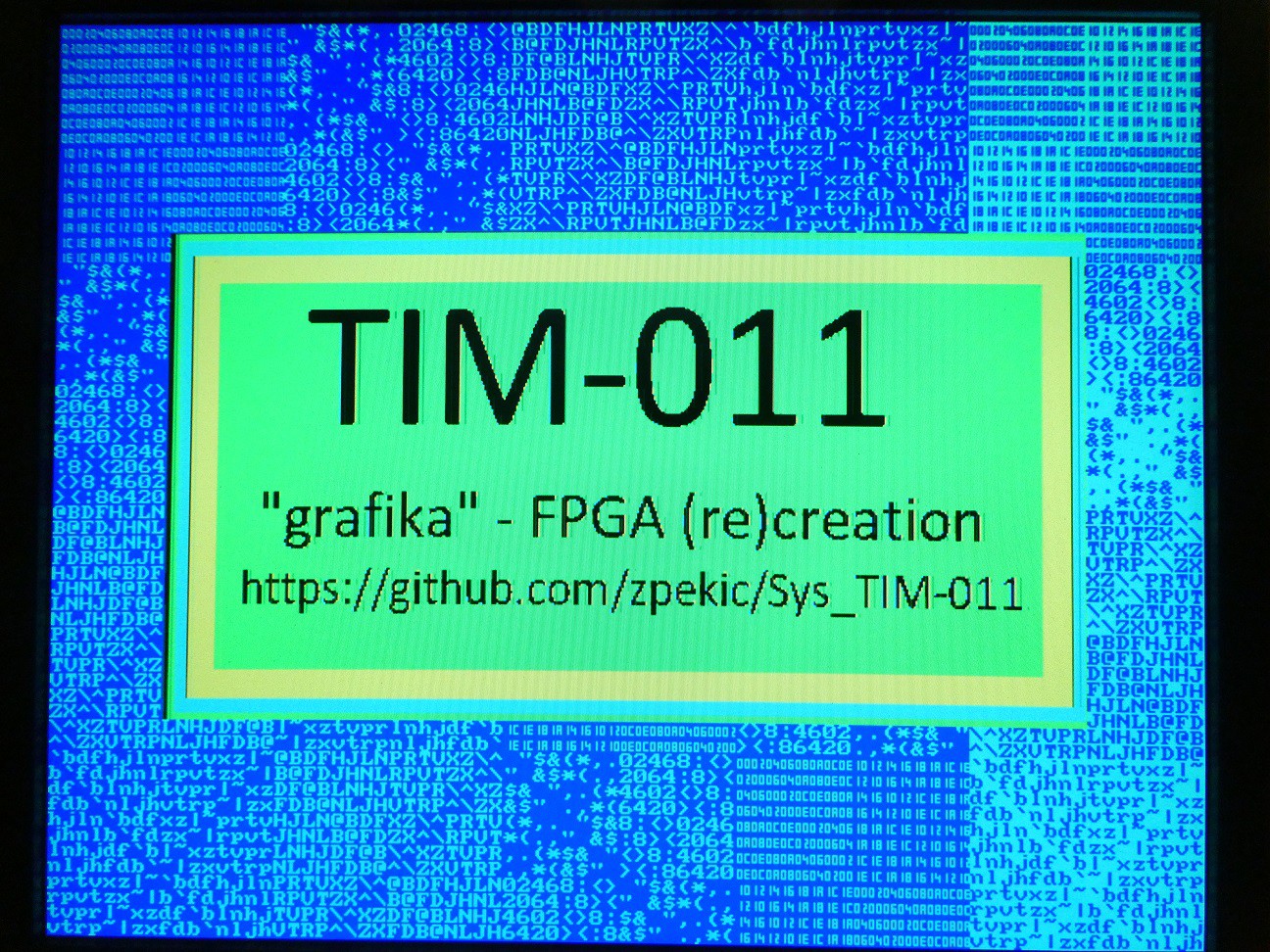
Perhaps not clearly visible, a picture from the VGA screen (generated by sampler + VGA controller):
Now looking at screenshot from GONBES-8200, it has different problems:
- top few lines dancing
- distorted height / width ratio
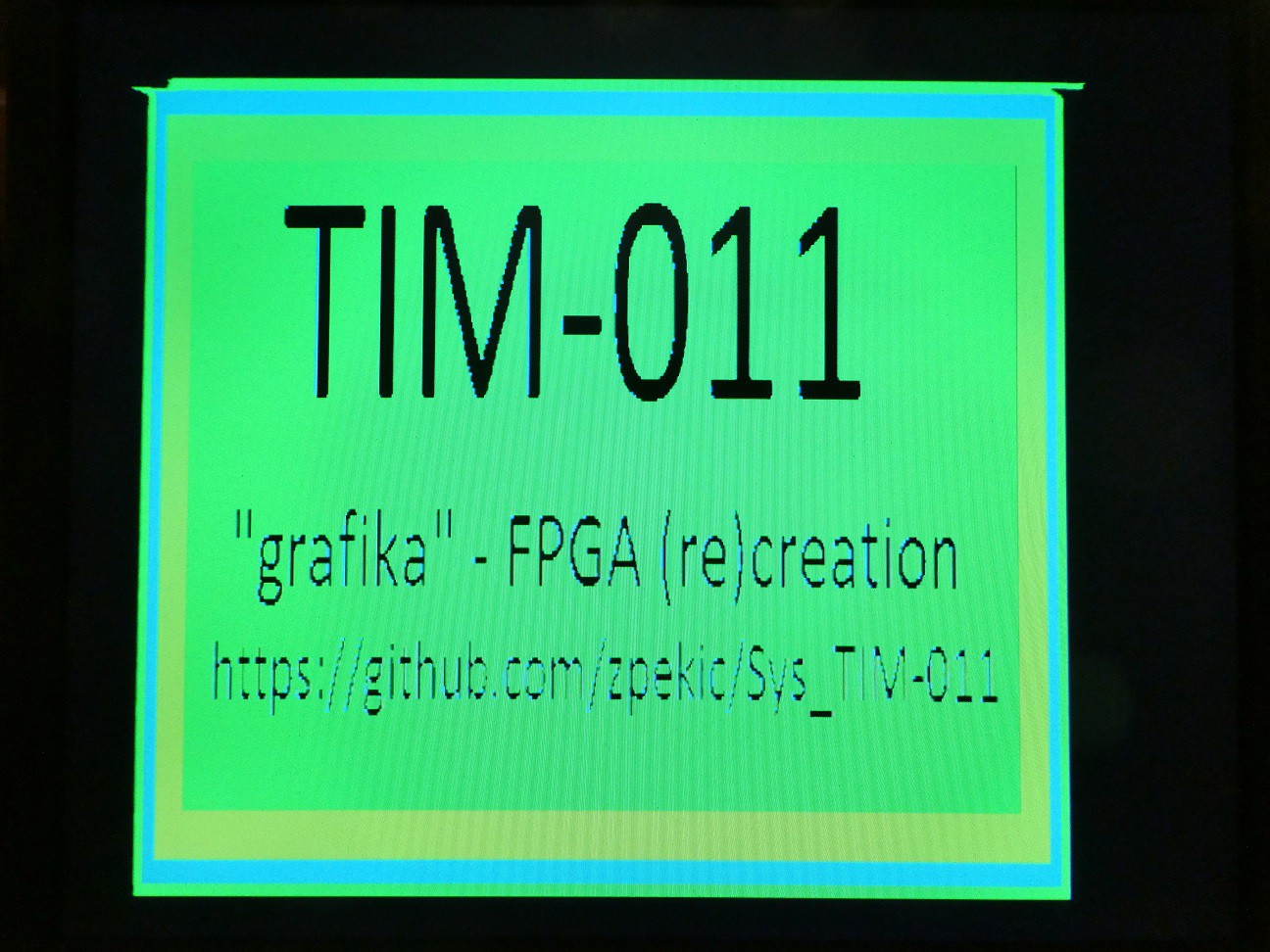
So in some ways, both are "worse" but the vertical bar artifacts are very annoying. I haven't tested if those would prevent reading of text on the TIM-011 display.
First, I thought that the image would deteriorate going from left to right, due to the skew between video signal to be sampled and the sampling clock - after all they are synchronized only once per line using hsync signal, and by 512th video signal (or 2048th sampling clock) they could be slightly off. But that is not the case, the quality is evenly good (or bad).
So the artifacts must come from the sampling approach itself. To "debug" it, I feed the sampler with 6 extra signals that control the sampling.
tim: tim_sampler port map (
		reset => RESET,
		clk => freq48M, -- 48MHz (4 times oversample of 12MHz)
		hsync => TIM_HSYNC,
		vsync => TIM_VSYNC,
		v2 =>	TIM_VIDEO2,
		v1 => TIM_VIDEO1,
		a => sampler_a,
		d => vram_dina,
		--limit => switch(7 downto 2),
		-- best result with sampler "algorithm"
		-- s2 from raising edge sample
		-- s1 from raising edge sample
		-- 4 out of 4 sample: on
		-- 3 out of 4 sample: on
		-- 2 out of 4 sample: off
		-- 1 out of 4 sample: off
		limit => "111100",
		we_in => we_in,
		we_out => sampler_wr_nrd
	);
The two MSB of the (not very well) named "limit" are consumed by the tim_sampler.vhd to select if for the v1, v0 video signals should be captured at the rising or falling edge of the sampling clock (s2 and s1 are 16-bit shift registers, clocked at 4*12MHz rate and ingesting the TIM-011 v1 and v0 video signals):
generate_s: for i in 15 downto 1 generate
begin
	s2(i) <= s2r(i) when (limit(5) = '1') else s2f(i);
	s1(i) <= s1r(i) when (limit(4) = '1') else s1f(1);
end generate;
s2(0) <= v2;
s1(0) <= v1;
Answer: raising is much better for picture quality.
The 4 LSB are consumed in the "voter" circuit which gets 4 sample bits (per pixel) and has to decide if those 4 indicated "signal on" or off. It does that by looking at the sampled patterns:
	with value select vote <=
		limit(3) when "1111",	--4
		limit(2) when "1110",	--3
		limit(2) when "1101",	--3
		limit(1) when "1100",	--2
		limit(2) when "1011",	--3
		limit(1) when "1010",	--2
		limit(1) when "1001",	--2
		limit(0) when "1000",	--1
		limit(2) when "0111",	--3
		limit(1) when "0110",	--2
		limit(1) when "0101",	--2
		limit(0) when "0100",	--1
		limit(1) when "0011",	--2
		limit(0) when "0010",	--1
		limit(0) when "0001",	--1
		'0' when others;	--0
Obviously, if no bit was sampled "1" then the output must be "0" - this is the last, default line. But what if it was sampled one of more times "1"? In that case, the output is controlled by selecting on or off individually each combination with 1, 2, 3, or 4 bits sampled "1" (a simple 16->1 MUX).
Through visual experimentation, turns out the best result is enable 4 and 3 bit "1" sample combinations, but not the 2 and 1 bit ones (1 results in unstable pic, 2 is effectively a no-op).
Discussions
Become a Hackaday.io Member
Create an account to leave a comment. Already have an account? Log In.