 Sasha Shturma
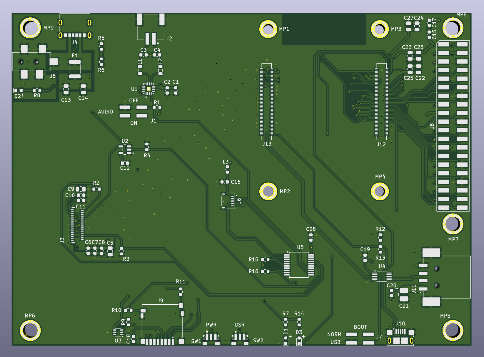
The board will have:
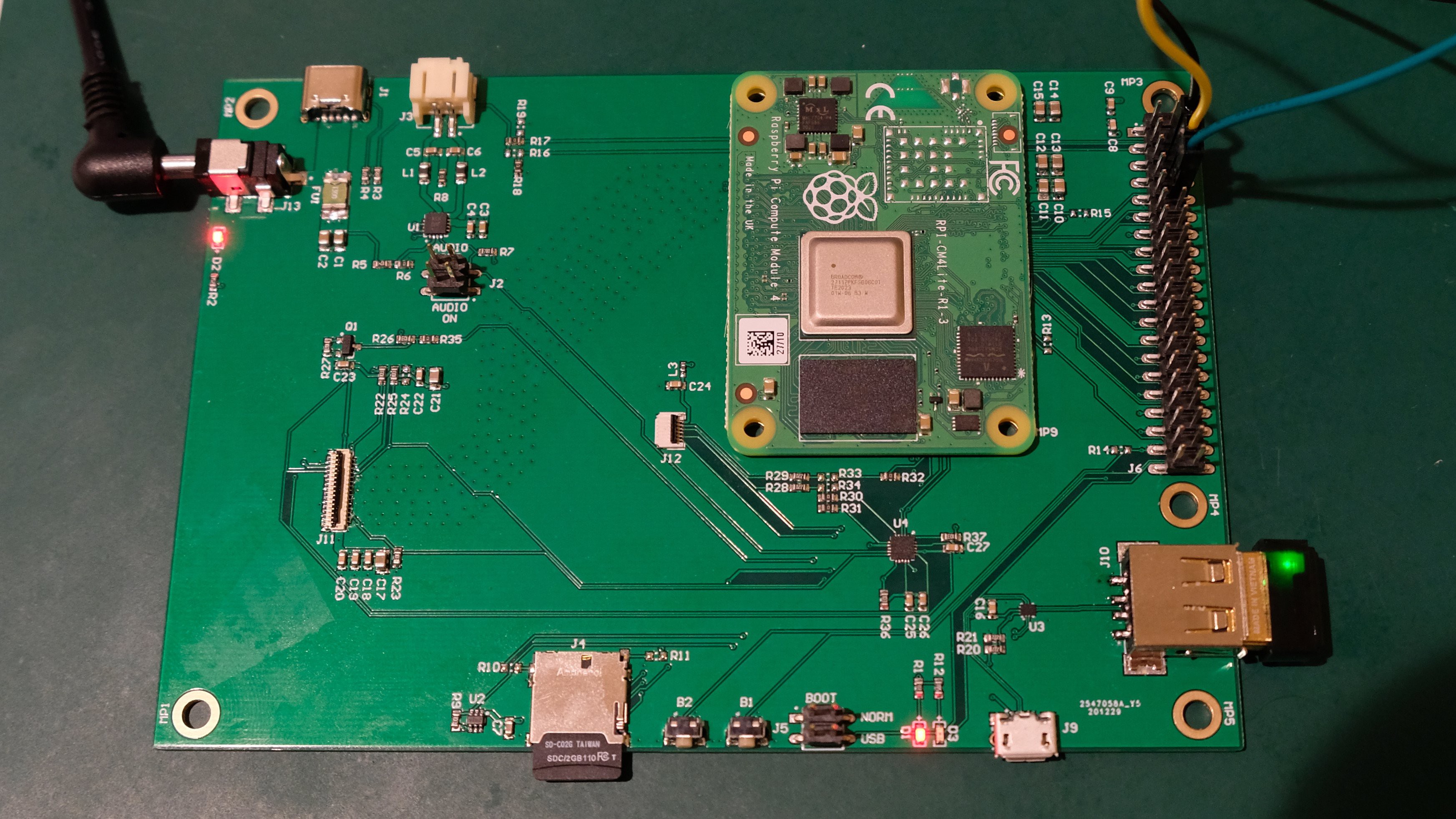
- standard RPi 40-pin header for peripherals and integration
- connector with 4-lane MIPI DSI interface for display
- connector with I2C interface for the touchscreen
- micro-SD card holder
- USB 2.0 host connector
- PCM audio amplifier with 3W speaker output
- USB-C power connector
- micro-USB connector for flashing the on-board eMMC
- general purpose push button
- power and activity LEDs
- mounting standoffs
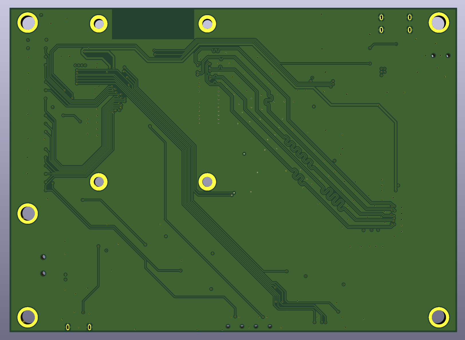
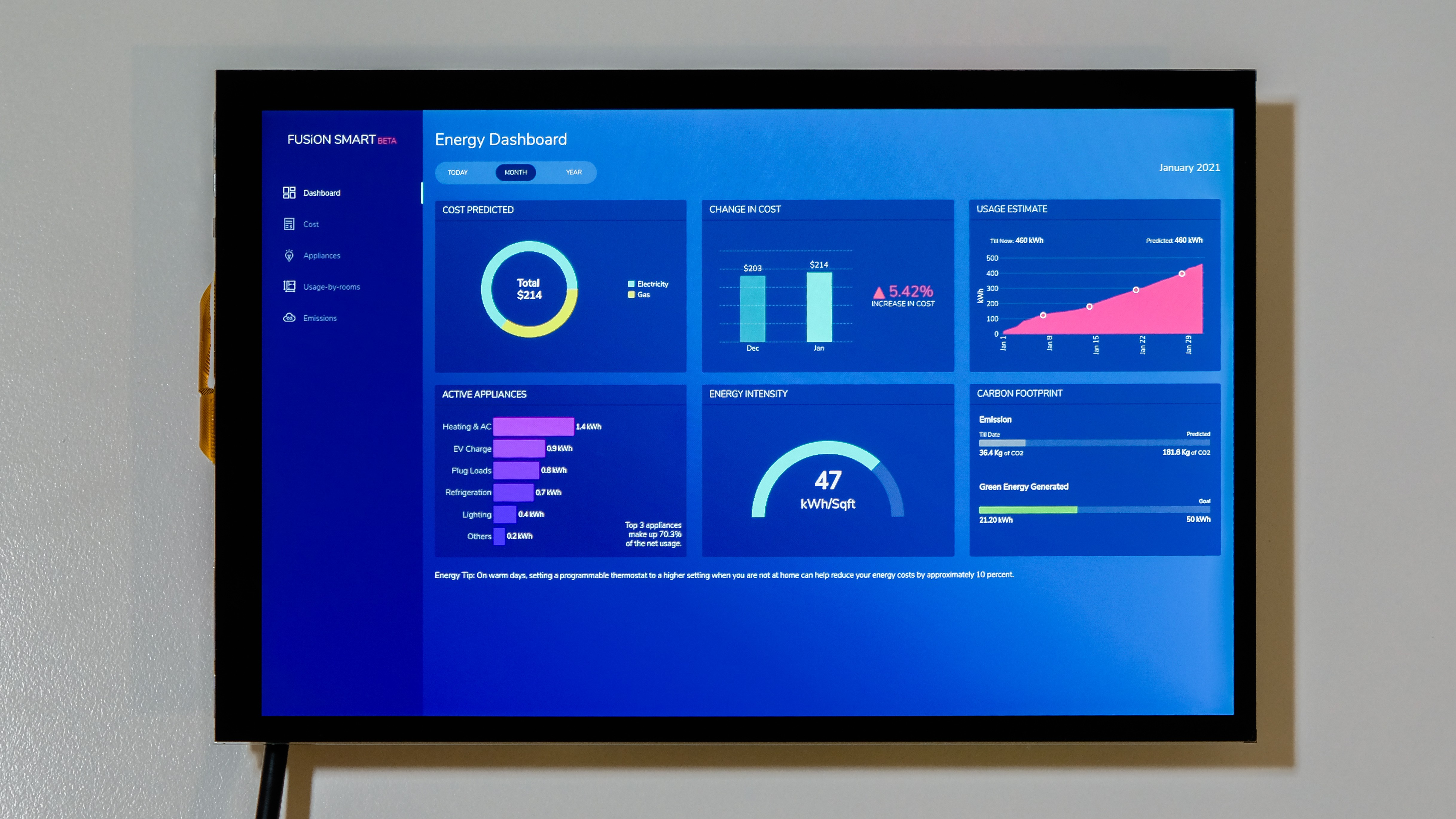
All components are surface-mounted on one side, making the resulting assembly slim and good for wall-mount applications like a smart home dashboard.
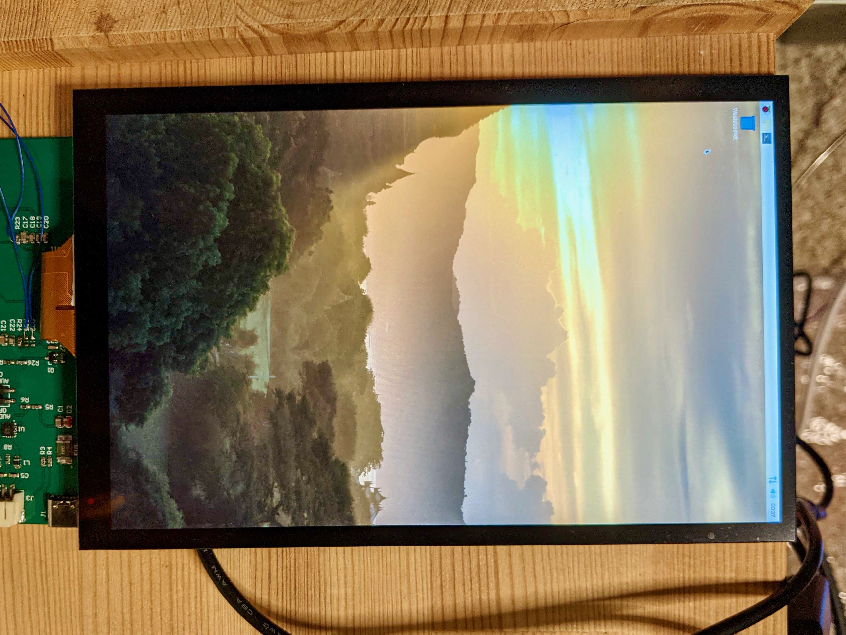
There is a challenge to overcome: we need to hack our way through the undocumented MIPI
DSI peripheral to make the interface work. With the CM3+ module, we used an HDMI-DSI bridge, which is an expensive and hard to source component. This time we want to do things differently and connect the interface directly to the Raspberry Pi Compute Module. Broadcom and Raspberry Pi Foundation are hesitant to release the documentation for the peripheral and reserve this interface for official displays. However, the source code for the driver is available, giving us a good starting point. We may need to adapt it to our display and switch the interface from 2-lane to 4-lane mode to support the higher resolution.
Let's start hacking.


 Bradley Austin Davis
 j0z0r pwn4tr0n
I was wondering how difficult it would be to create a board that could drive a laptop screen to do away with the HDMI LCD driver board.
It would be something like the ebay listings advertised as "HDMI VGA 2AV Reversing LCD Driver Board for 13.3" LP133WH2 1366x768 LCD panel" but cutting out the HDMI cable, separate driver board, multiple power supplies etc
I have been looking at options for connecting a pi running magic mirror (or similar) to an LCD to put behind a mirror but making it as thin as possible.