 David Tucker
I have been interested in building a CNC machine for years, even going as far as building one out of old CD Rom drivers, and another from an old 3D printer. A year ago I stumbled onto Nikodem Bartnik's DIY 3D Printed Dremel CNC project and found the inspiration I was looking for. I took his excellent ideas and built my own version of his machine. That machine was great, but was lacking in several ways so I sat down for this second redesign and think I finally hit upon a great combination.
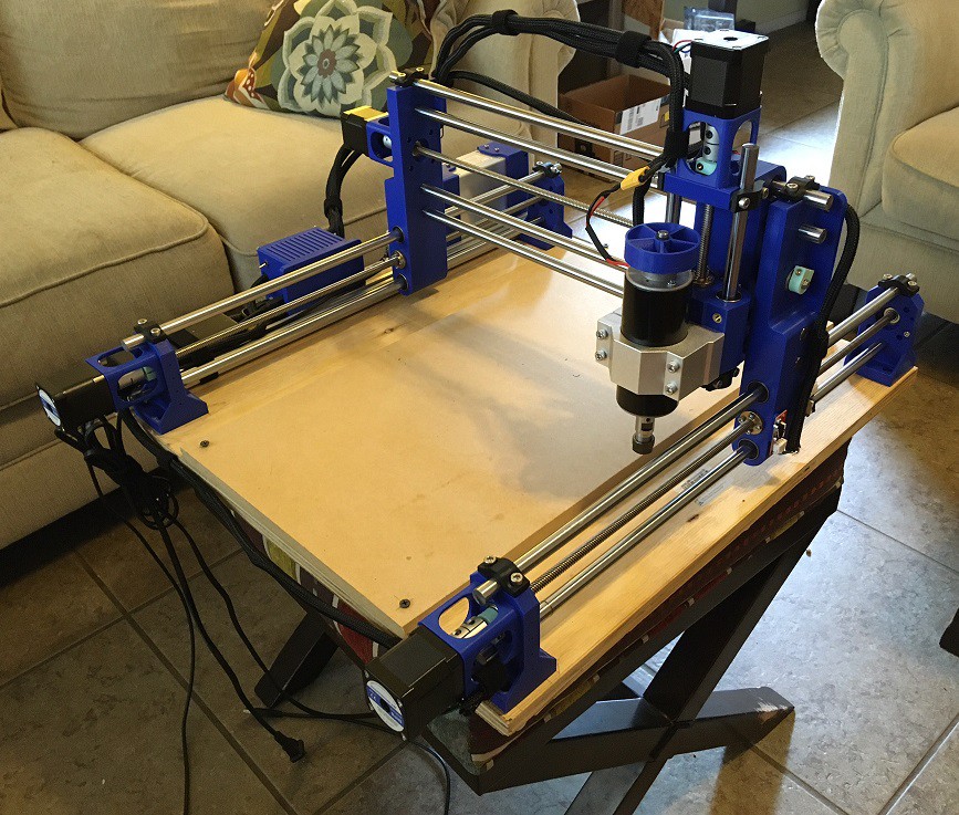
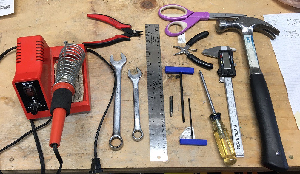
The project goal was to make a machine that had a working size of at least 11"x17", the final working volume ended up being 365 mm x 465 mm x 75 mm (14"x18"x3"). To make it as inexpensively as possible. And to make it accessible so that anyone with a 3D printer and a few simple hand tools could put it together. All while being capable of doing serious milling of hard woods and aluminum.
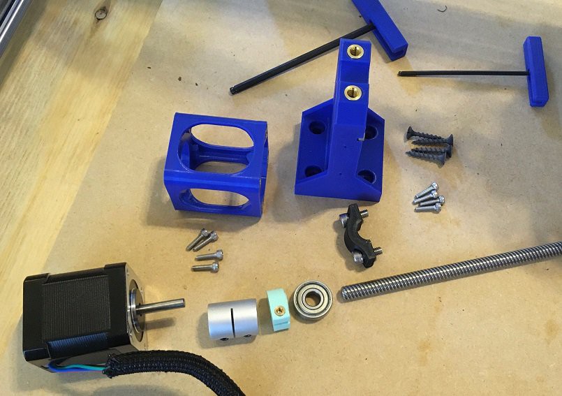
Here is a full parts and price list for the machine.
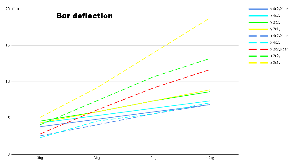
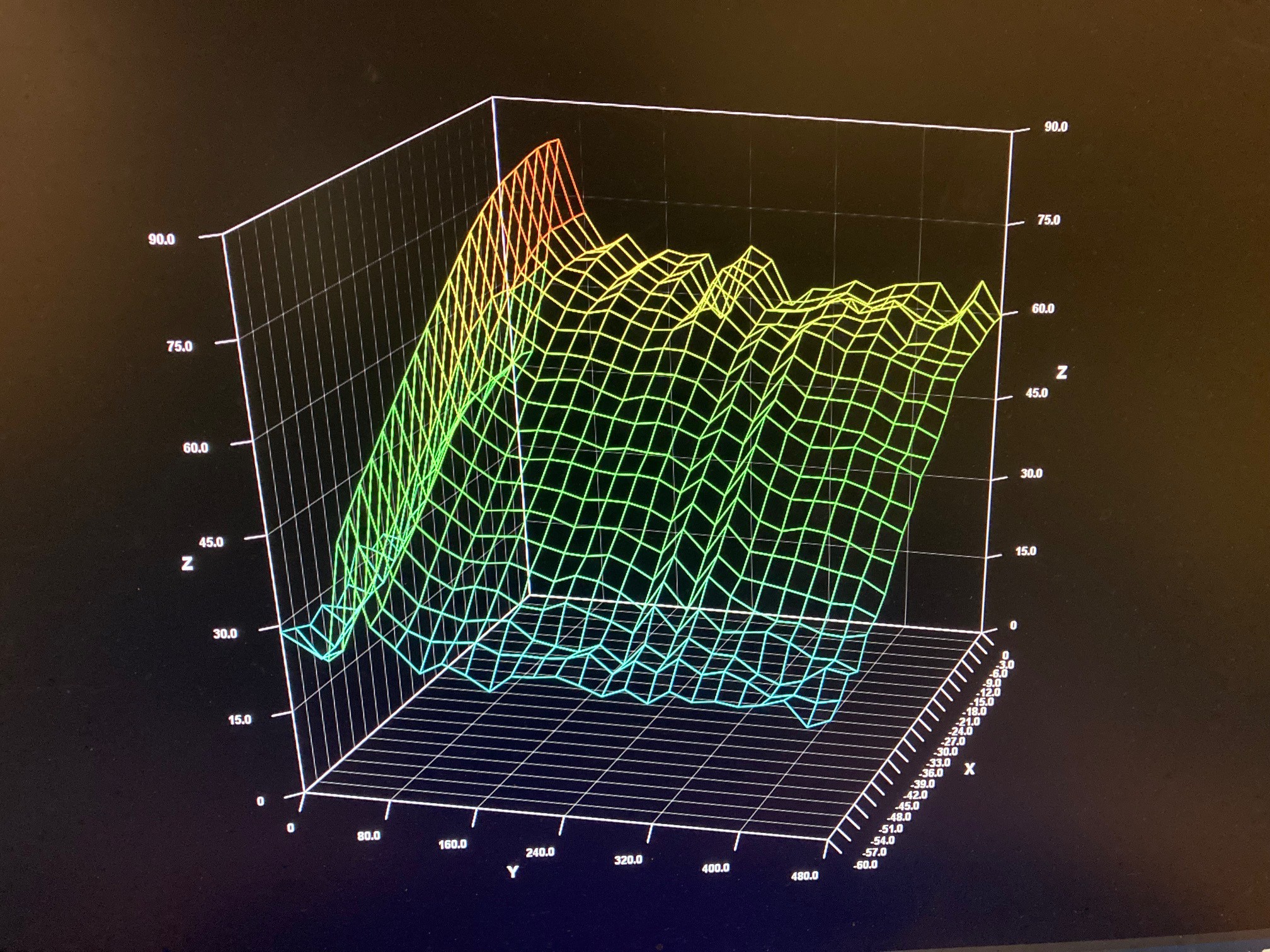
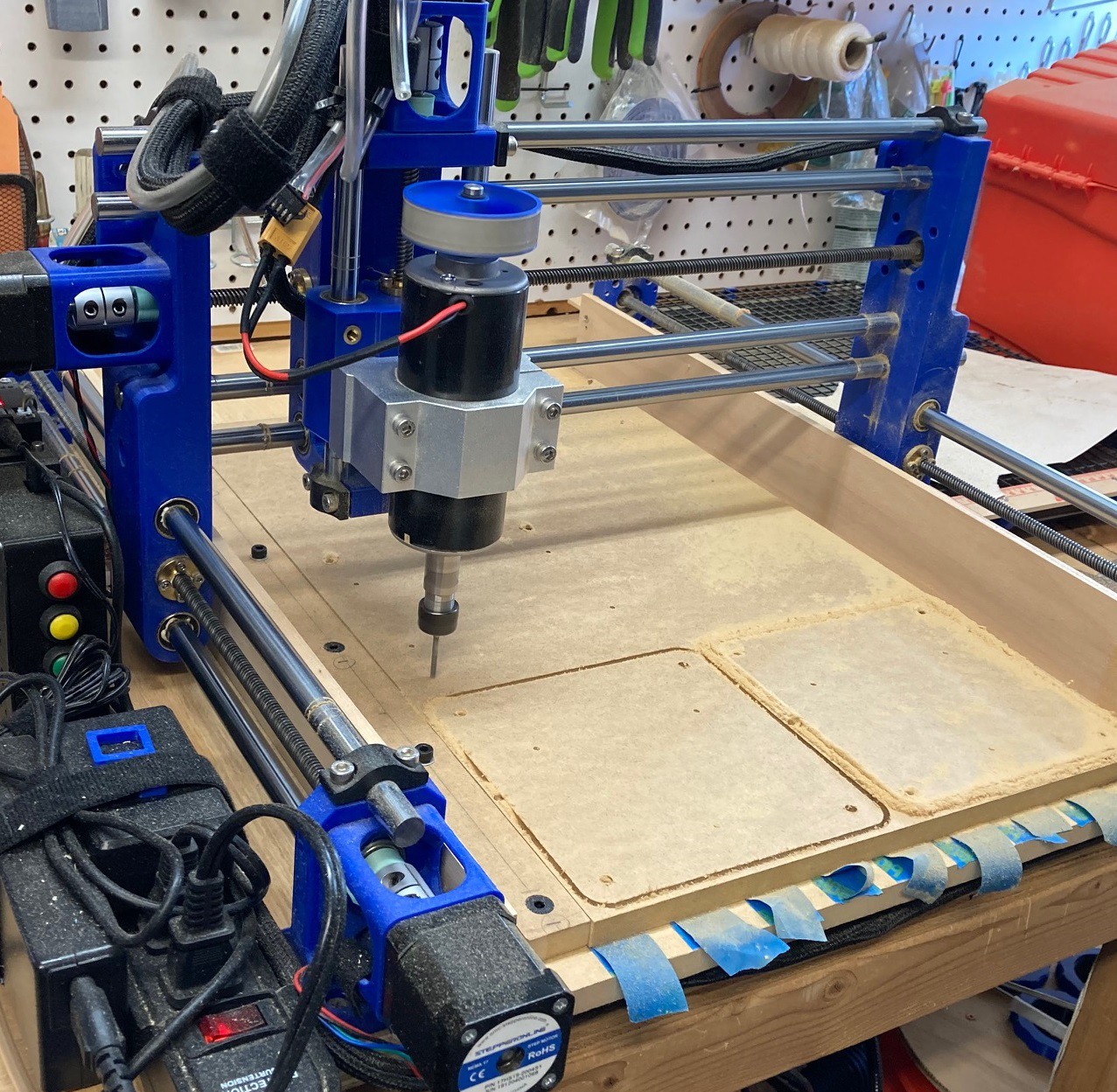
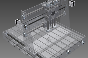
I'm using 12 mm smooth rods and LM12LUU bearings for the linear motion because they are readily available and very low cost. However at the size were working with the 12 mm rod is not stiff enough. After running tests with different configurations of rods I settled on doubling up the rods, that is almost half the cost of using 16 mm rods while still being significantly stiffer than a single 12 mm rod. You can see from the graph below that deflection at the tool in the X and Y direction is greatly reduced with doubled up rods.
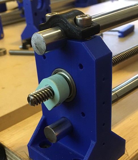
I'm using 8mm Acme trapezoidal lead screws for the drive system. In the original design I was getting a lot of backlash. I experimented with several different configurations but finally landed on combining a brass nut with a Delrin nut in compression to eliminate backlash. This is easier to adjust than using two brass nuts, safer than using Delrin nuts, and much stiffer than using spring based backlash nuts that you can find on Amazon and AlliExpress. The Delrin nuts are just flexible enough that you can have a fine control over tension making it easy to dial out backlash without adding a lot of resistance to the setup.
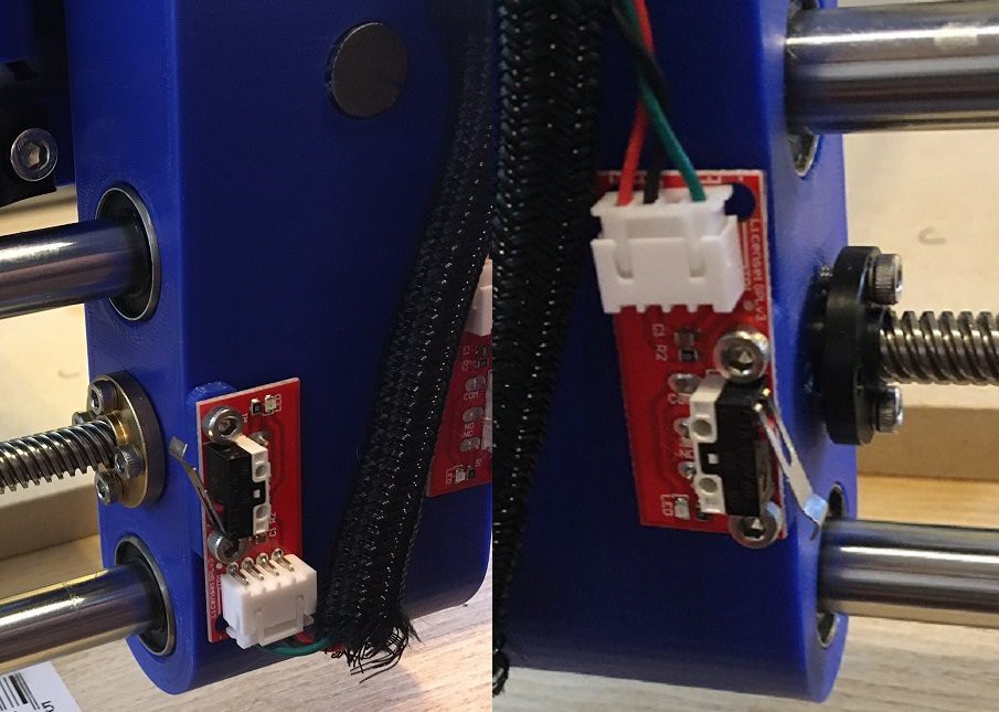
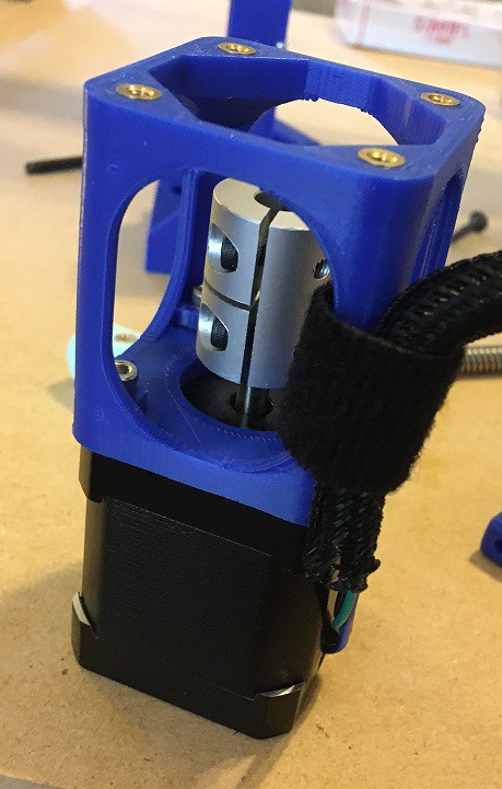
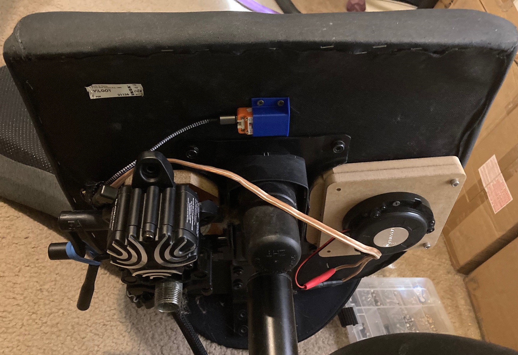
In my original design I was relying on the bearings in the stepper motors to take all the load from the lead screw. This was not a good arrangement and on some of my axis I was able to deflect the drive shaft by several mm. I worked around this by adding skateboard bearings on each end of the lead screw and using 3D printed nuts to tension the lead screw between the bearings. This provides a lot of strength and completely decouples the stepper motors from the system. I also added standoffs to the stepper motors to make maintenance easier and to ensure I can use every inch of my linear rod for motion.
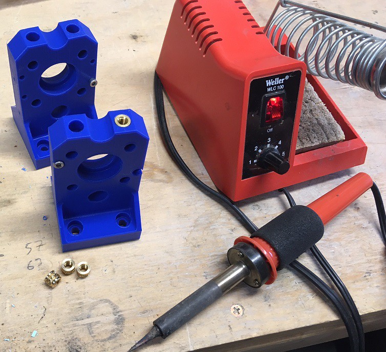
I struggled for a long time with the 3D printed parts cracking under load. I have gone through many design iterations trying to come up with a clamping and screwing system that can handle the forces of a milling machine without sacrificing the convenience of a 3D printed part. Eventually I hit on the idea of using heat set brass inserts to strengthen the screw holes and using separate clamps to hold my rods in place. This has proven to be quite robust and requires a minimal amount of effort to put together. You do need some sort of a heat source to set the brass inserts. This has the added benefit of making the machine very serviceable, it is easy to take it apart and put it back together now without worrying about damaging the 3D printed parts. Well worth the small increase in cost and complexity in my mind.
As much as possible I have tried to make the parts symmetrical for easy reuse, and have carefully designed all parts to be printed as designed without needing any supports or brims. The goal is to take out the complexity as much as possible so a...
Read more »


 Kert
Kert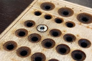
 Timo Birnschein
 Hari Wiguna
Hi All.. looking into building this... my first time with a CNC.. @aiasnikov , did you get to build with the Makita router? Anyone else used a router as spindle? Love the idea, mostly to avoid another piece of single use hardware in my basement...but worried about the added weight.
Thanks in advance for sharing any experience.
ET