 David Tucker
I have been trying to work out the math behind how a laser diode is focused. There is a lot of talk out there about what lens or focal distance works best but I'm struggling to find any actual hard proof of how it all works. It seems to me that if one focal length works better than another that we should be able to prove it mathematically.
I came across a writeup on Gaussian laser focus, and another on Math behind a collimating lens. In order to follow the equations we need to measure some details on our lasers. First up was the focal length of the lens.
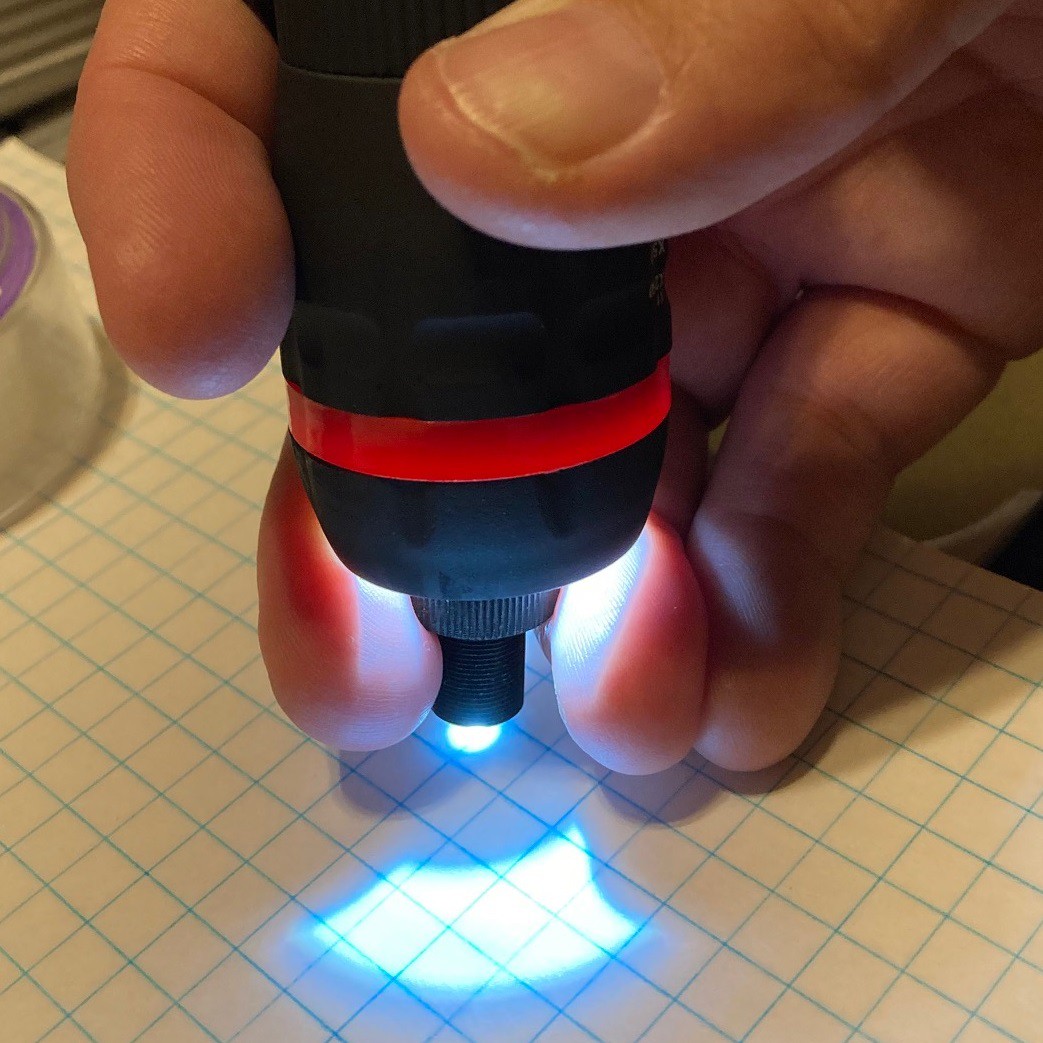
This is a single element convex glass lens that is about 6 mm in diameter and 1.5 mm thick. To measure the focal length of the lens I shined a flashlight through the lens and focused the resulting light at a piece of paper. By measuring the distance to the paper, as well as how deep the lens is in the holder we can work out the final focal length. In this case I measured it at around 7 mm, give or take a mm. It is not clear in the image above because it is blown out, but the focal point is only a pinprick.
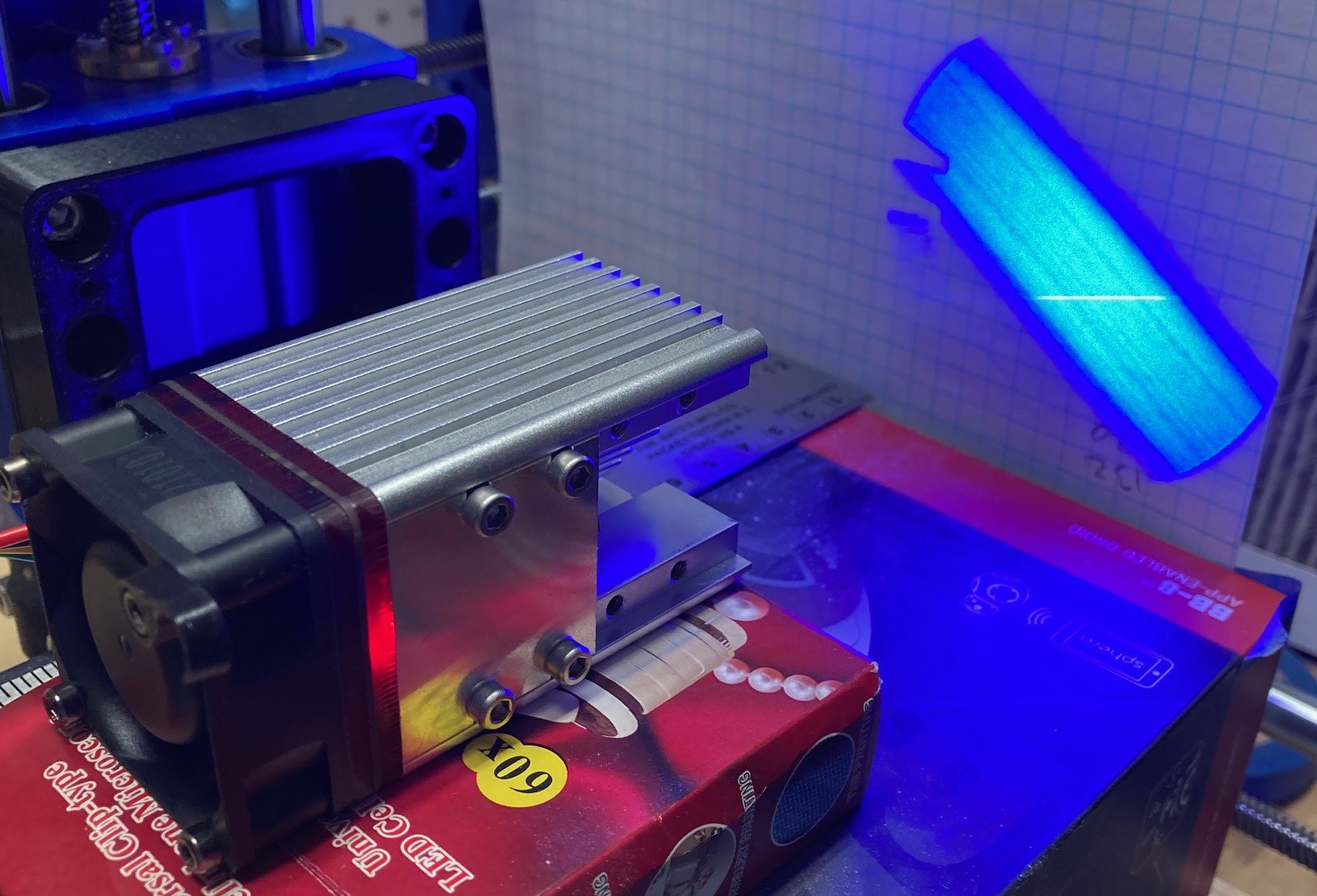
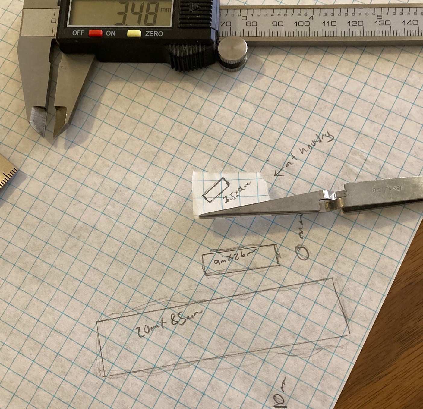
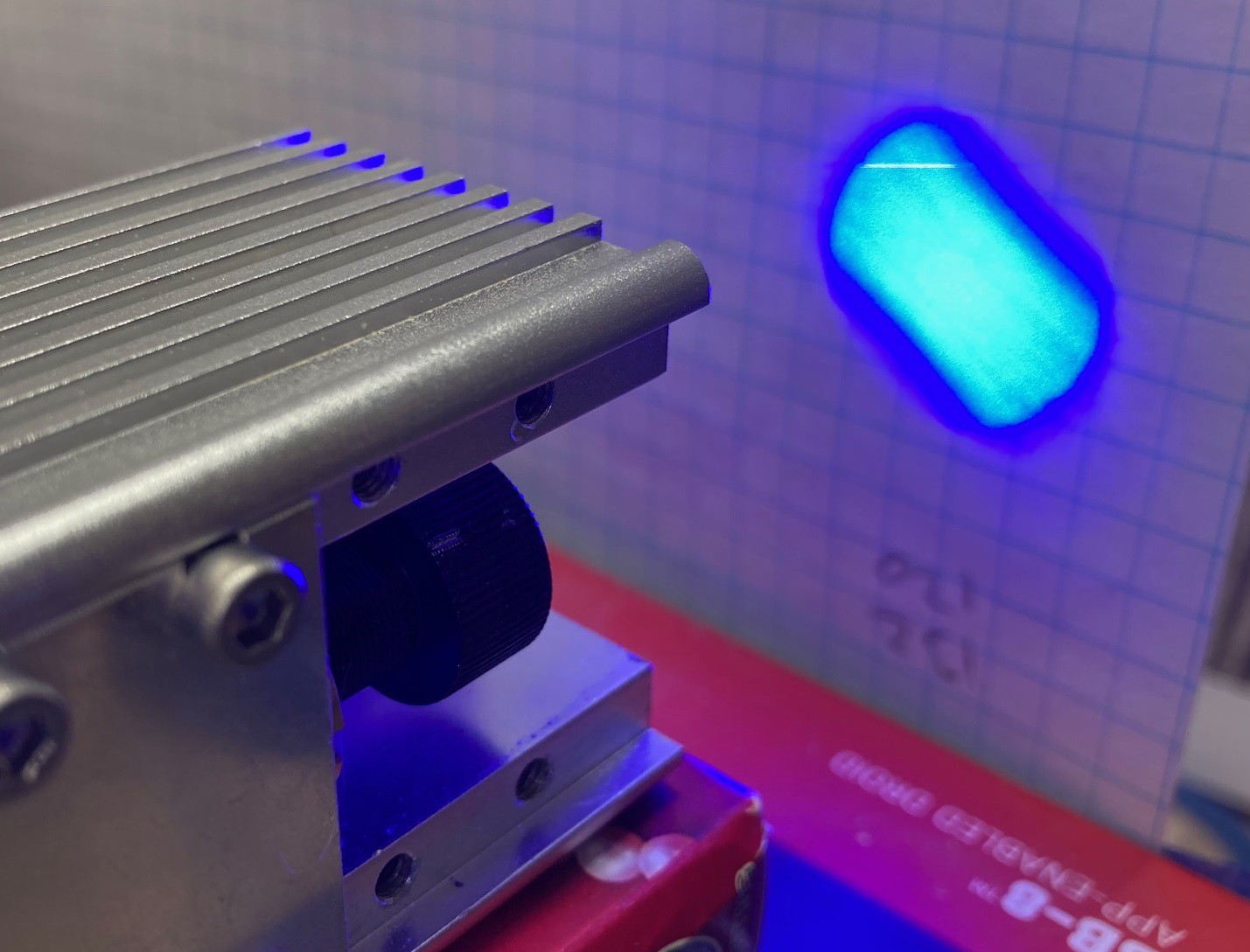
Next I wanted to work out the angle of divergence of the laser diode. I removed the lens and shined the laser at a piece of paper at fixed distances and then used a marker to outline the shape of the beam. I did this at 100 mm from the base of the silver housing, 0 mm from the base of the silver housing, and right at the end of the brass tube that the lens fits into.
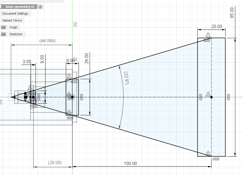
By plotting out the measurements and connecting the dots we can approximate where the origin or focus point of the diode laser is and its relationship to the lens.
One thing to notice right away is how fast the fast axis spreads out. The lens we are using has an aperture of only 5.5 mm with the retention ring in place. That limits how far away from the laser you can move the lens before the housing starts to seriously block the edges of the light. Here is an example with the lens screwed out about half way in the housing. Notice that we are blocking about 1/3 of the laser light!
Given the above information and by experimentation we can work out the practical limits on our focus range. With the lens screwed all the way into the housing we get a focal distance of about 40 mm from the base of the laser. And with is screwed out 2 mm from the housing we get a focal distance of 0 mm from the base of the housing (as close as physically possible).
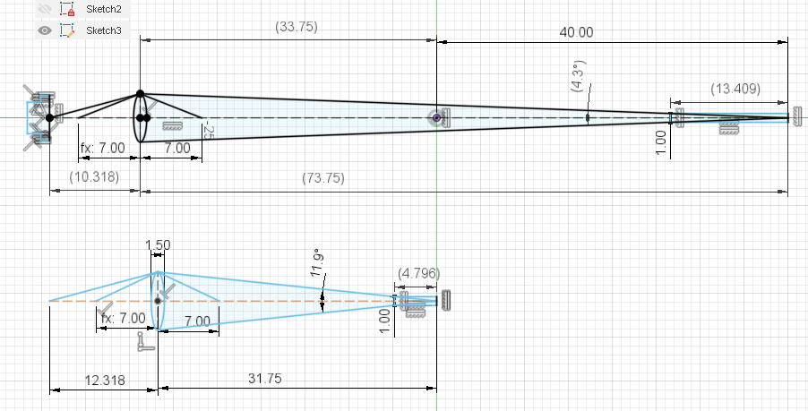
Putting it all together we can work out the geometry of the lens, focus point, and laser. Using the thin lens formula from the articles linked above we can plug in the above values to double check them. The thin lens formula is:
Where s is the distance from the laser to the lens, s" is the distance from the lens to the focus point, and f is the focal distance of the lens (7mm). Doing a bit of algebra we can solve for any variable. In this case lets solve for f and see if we were close on our lens focal length. A little algebra gives us:
Plugging in 10.318 and 73.75 for s and s" we get an f value of 9.1 mm, and plugging in 12.318 and 31.75 in for s and s" we get an f value of 8.9 mm. I think that I must have measured the lens incorrectly and it is in fact a 9 mm focal length lens, although it is possible some other part of the measurement was wrong.
Anyway this does not solve the problem of knowing what focal length is better but it does get us a bit closer to understanding how the laser works.
You can see in the last image that a longer focal length does make for a more narrow beam, and that should translate into better performance when cutting material. I marked out the depth each would cut if they removed 1mm of material, you can see a large increase in depth with the 40 mm focus height (from the bottom of the housing). I will try to setup a test to verify this one way or the other.
Discussions
Become a Hackaday.io Member
Create an account to leave a comment. Already have an account? Log In.