 David Tucker
Edit, fixed some bugs with the equations.
---
For my rotary project I needed to 3D print a gear that would interface with a toothed timing belt. However when I tried to wing it and make one without doing any real research the belt did not interface with the gear very well. After doing some research online I came across this guide that provided some good inspiration.
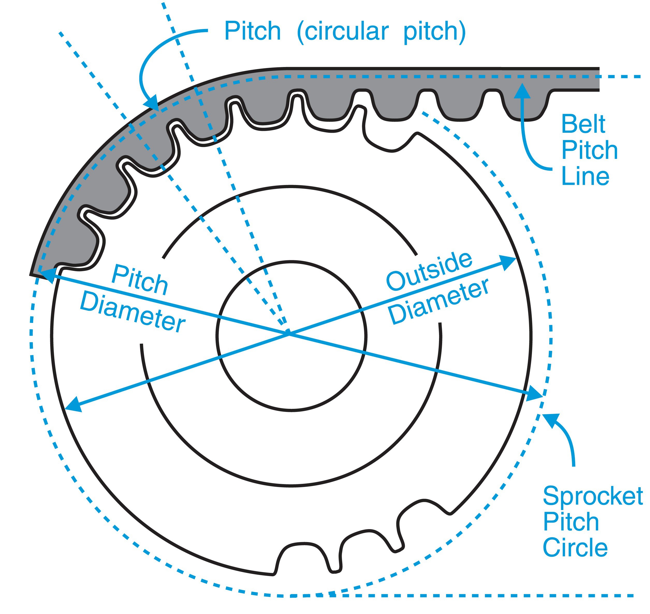
On the face of it this appears very simple. I have a belt with 2 mm spacing on the teeth, I'm looking to make a pully with 20 teeth so I need it to have a circumference of 40 mm. Using a handy circumference calculator online I worked out that my gear has a diameter of 12.732 mm.
However that is an overly simple view of the process. The above is true, but the belt itself will be wrapped around our gear, and in the process it will stretch a bit on one side and be compressed a bit on the other. It turns out the line where the belt neither stretches or compresses is half way through the belt itself (no including the teeth).
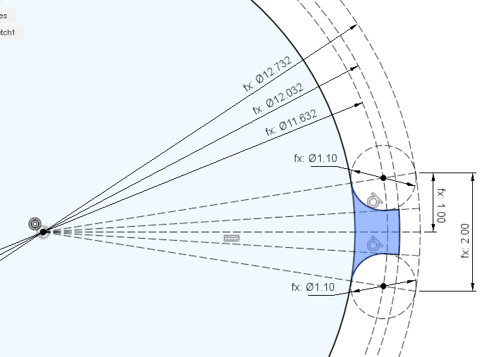
Given a diameter for our gear (12.732 mm), we subtract the width of the belt (1/2 width on each side of the diameter) to find the outer face of the gear (12.732 mm - 0.7 mm = 12.032 mm). The teeth on the belt are made of half circles that are 1 mm in diameter. To add a bit of clearance I added 0.1 mm of padding around each tooth, that should cover any inaccuracy's in the printing process. The height of the tooth is 0.7 mm, just a bit more than the 0.5 mm if the tooth would form a perfect sphere.
Once you have your tooth designed then extrude the body of the gear and the one tooth as a separate body. Add a small bevel to the edge of the tooth to make it move in and out of engagement with the belt smoothly.
My belt is 6 mm wide, so I made my gear 7 mm wide plus 2 mm on either side for the edge that holds the belt onto the gear.
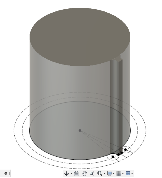
Next we select our new tooth and replicate it 20 times, remember to select it as a body ad not as a face. Finally use the merge tool to combine all the teeth together with our gear body. This is less cumbersome then trying to replicate the tooth in our original drawing.
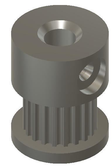
Once we have the teeth modeled then we can go ahead and polish it all up with a lip on either side to retain the belt, a hole in the center to fit our stepper shaft, and a hole to allow for an m3 bolt to lock it onto our shaft. Notice that I beveled the upper flange at a 30 degree angle (give or take) so that this can be printed in place. It may have been better to invert the design so the taller flange is flat on the bed, that would minimize the chance of failure if the bevel was not sufficient.
If you need to calculate the (approximate) spacing between two gears, given a known length of belt, then use this handy belt length calculator in reverse. Keep in mind that this is based on the center of the belt and not the diameter of the gear.
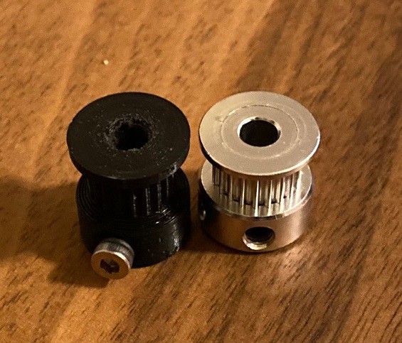
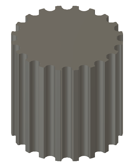
If we did our job right we end up with a perfect facsimile of a cast metal gear.
Discussions
Become a Hackaday.io Member
Create an account to leave a comment. Already have an account? Log In.