 David Tucker
Here is a project have been working on for several weeks now. I'm glad I finally have a chance to show it off.
So previously I stumbled onto the following formula that shows the relationship between speed, power and cut depth. This basically says that doubling the power or doubling the number of passes will double the cut depth (up to a point) or depth = power. While doubling the velocity (speed) will cut the cut depth in half, or more precisely depth = 1 / speed.

I ran a few experiments that illustrated this nicely, but they only capture one slice of the full picture.
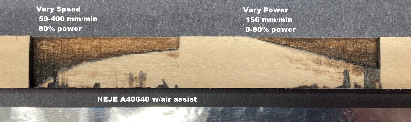
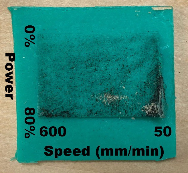
To better illustrate how all this works I wrote a new program that draws a series of lines, spaced 0.2 mm apart while varying power in the x direction between 0% and 80% and speed in the y direction between 50 mm/min and 600 mm/min. I picked up a piece of 20 mm thick basswood to run this experiment on.
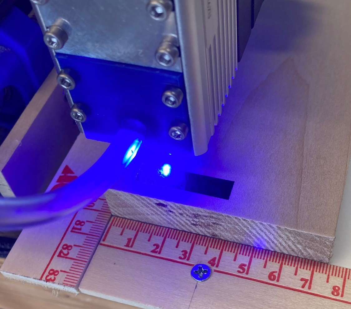
After letting this run for a few hours I ended up with this finished cut. It shows the relationship very nicely. However a picture just does not do it justice, it is impossible to really see the detail without holding it in your hands.
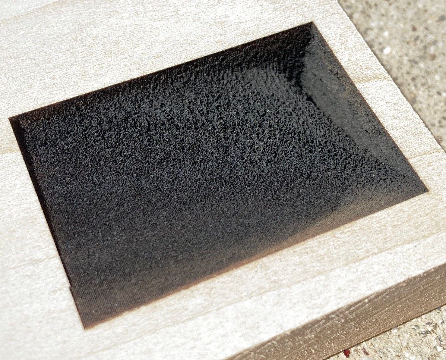
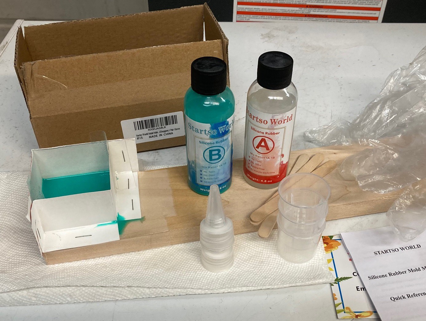
So I hit upon the idea of using a bit of silicon to make a cast of the cut so I could photograph it from several angles. I picked up the cheapest set of silicon I could find on amazon, figuring this would probably fail. However I was pleasantly surprised that it worked well.
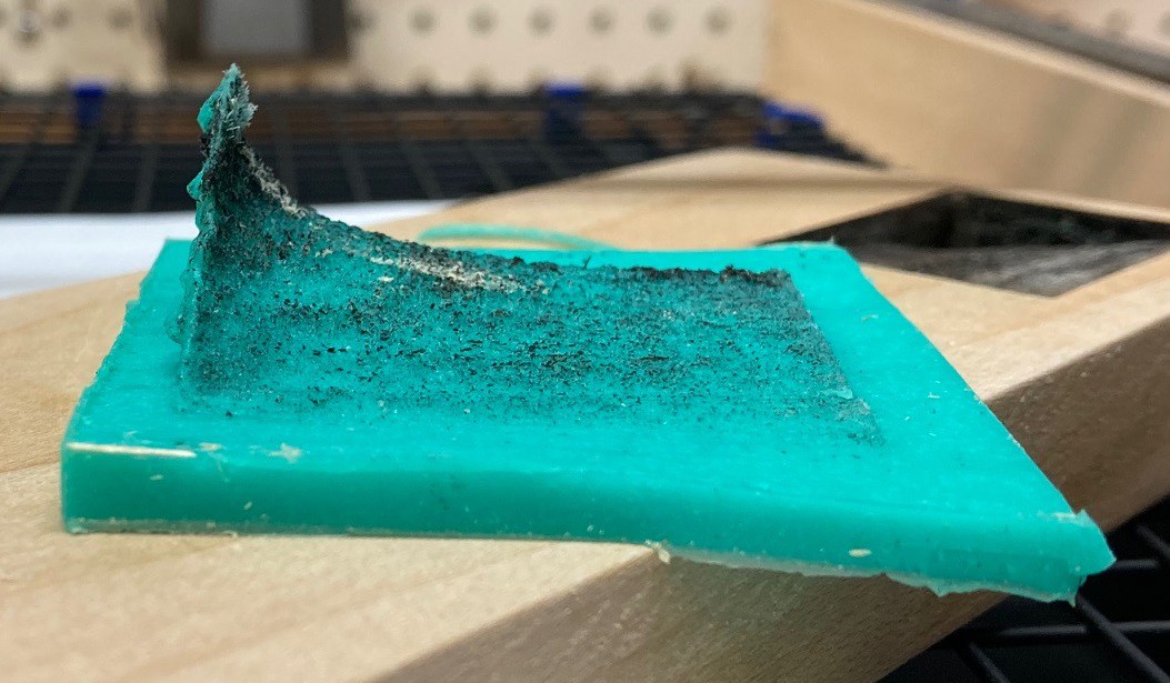
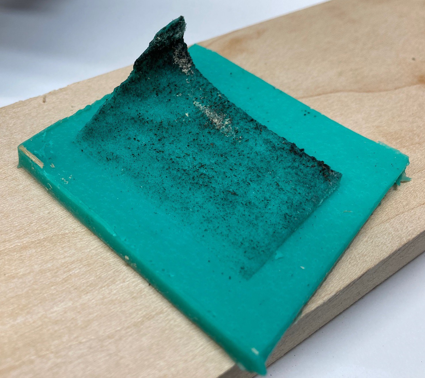
Here is the finished cast, fresh out of the mold. I believe I have captured every part of the cut, no material was left in the mold that I could see. It is crazy how much detail it was able to pick up. The tallest part of the spike is 19mm, this NEJE A40640 laser module can cut 19 mm in one pass, crazy!

Here is a top down view of the cast. I labeled the variables on the image. The spike is in the lower right corner of the image.
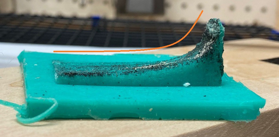
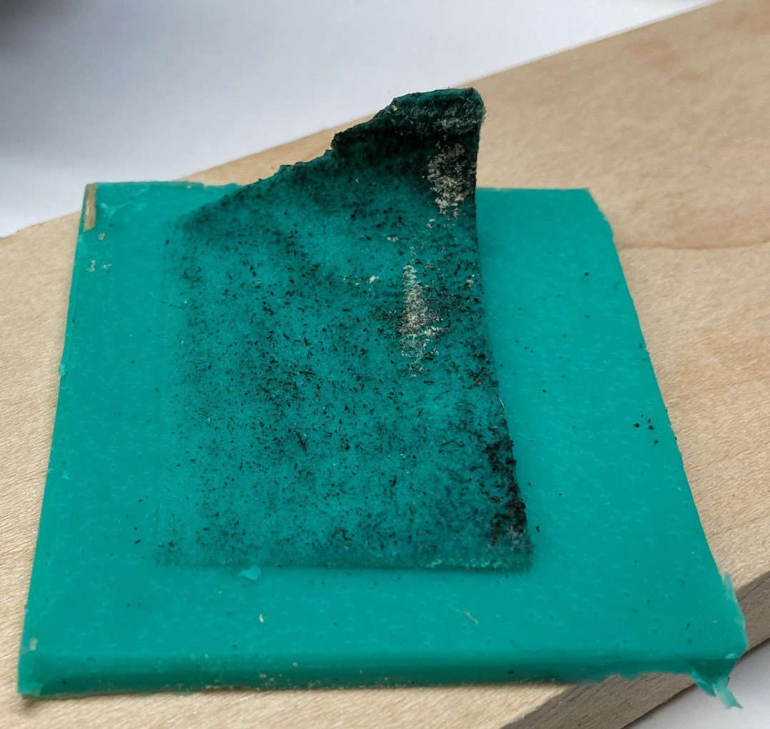
Here is a side shot showing the change in power. You can see that the resulting depth is approximately a straight line. It is a lot more straight at lower depths (faster speeds).
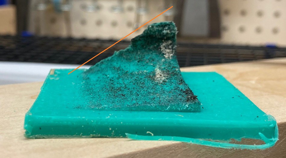
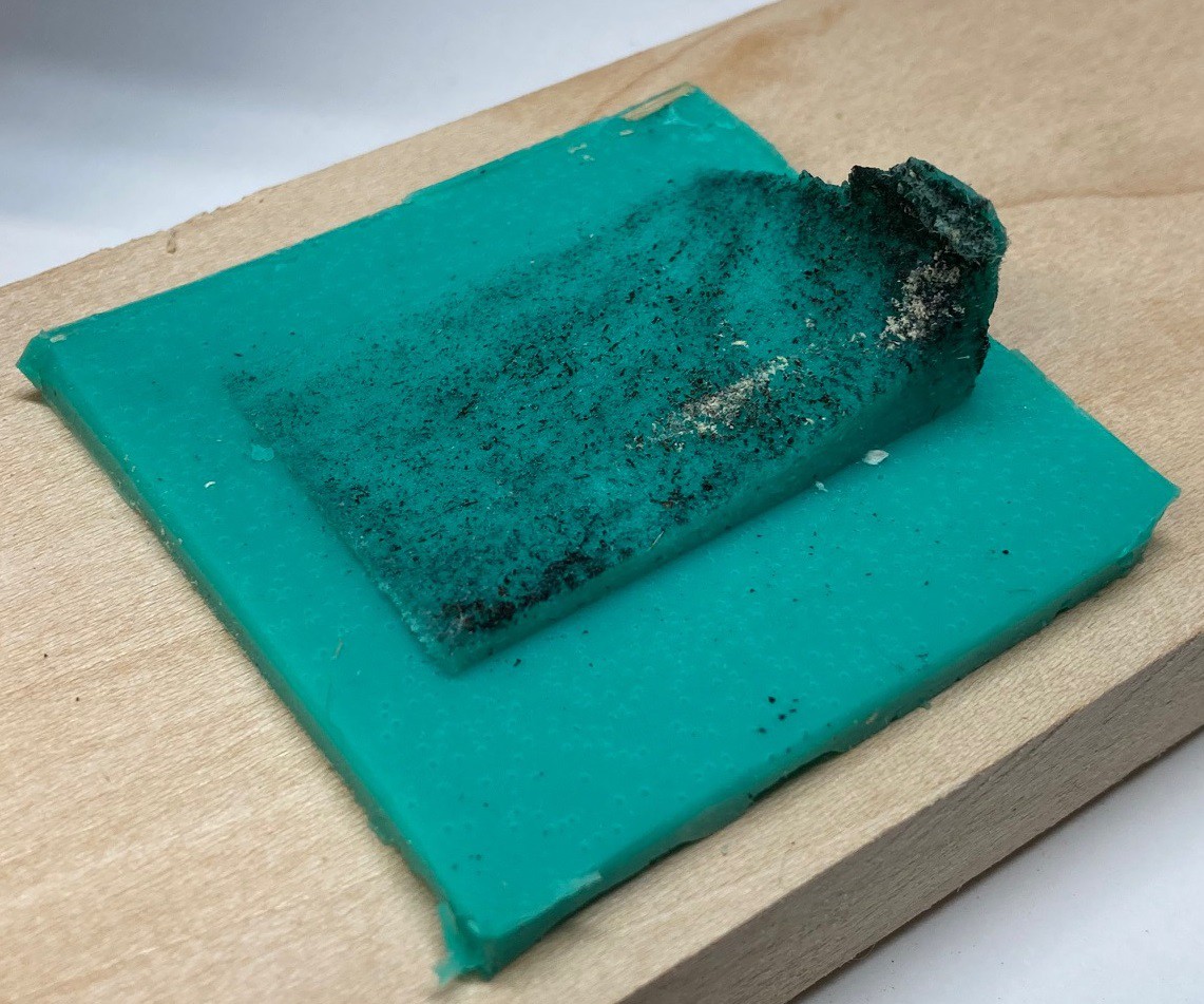
And another side shot showing the change in speed, you can easily see the inverse power (1/x) shape of the cut.
It is interesting to see both in the cut and in the cast that at the highest power at the slowest speed there is a lot of damage done to the material. We see the damage quickly fall off as the speed increases, by 100 mm/min it is looking much better.
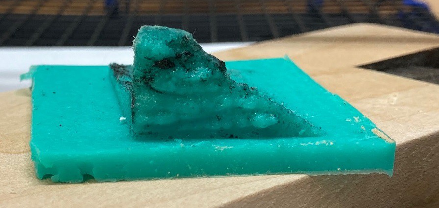
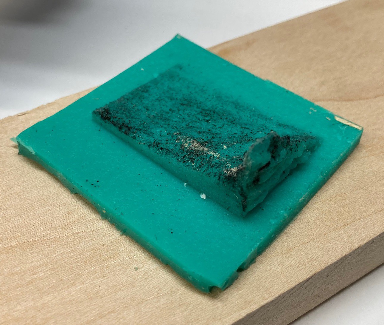
Here are several other shots from different angles.
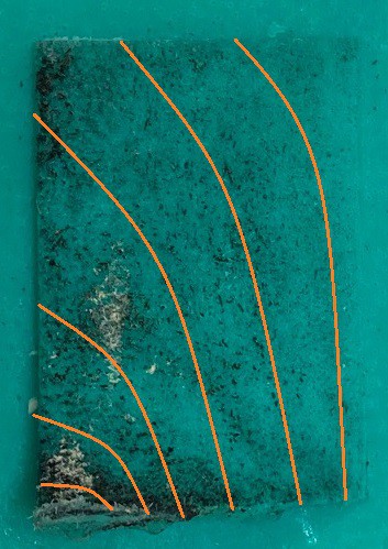
I have not found a good way to make topographic elevation contour lines on this, but if I did you would see that they are not straight lines but more or less C shaped curves that look something like this.
Discussions
Become a Hackaday.io Member
Create an account to leave a comment. Already have an account? Log In.