As winter started to show by shortening the amount of light coming though my windows, i realized that I was missing a crucial element on my work from home desk : a lamp !
I had a quick look on what was commercially available but nothing caught my attention...
So let's start an overly ambitious project instead and use that as a pretext to start some digital fabrication!
Main goals
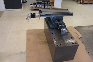
- learn how to use a CNC
- make a lamp
- have it look great with a tentacle-like arm
Secondary objectives
- make a cool start up animation
- be able to tune the light color to fit the time of the day
- motorize the tentacle with stepper motors
- have a through wood capacitive touchscreen to control those features
 Tested the setup with my RC transmitter:
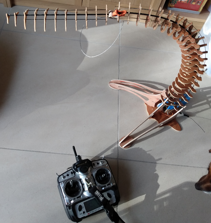
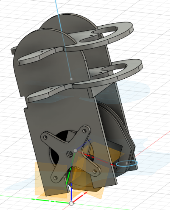
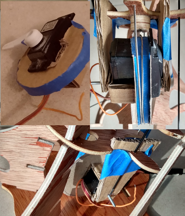
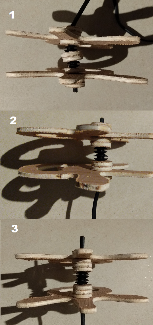
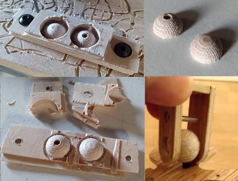 The result is really nice, the texture of the ball surface is a bit rough but helps to keep the joint rigid enough to support the weight of the head
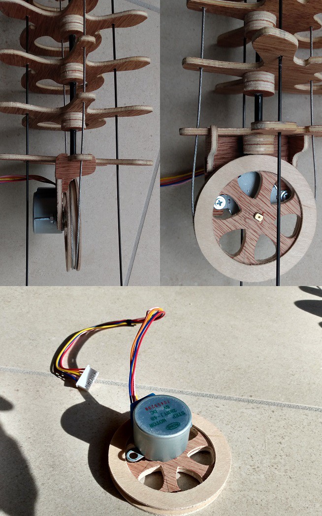 the first motor support i made in the picture above was not rigid enough and all the loads were on the poor stepper shaft.
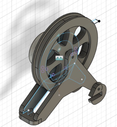
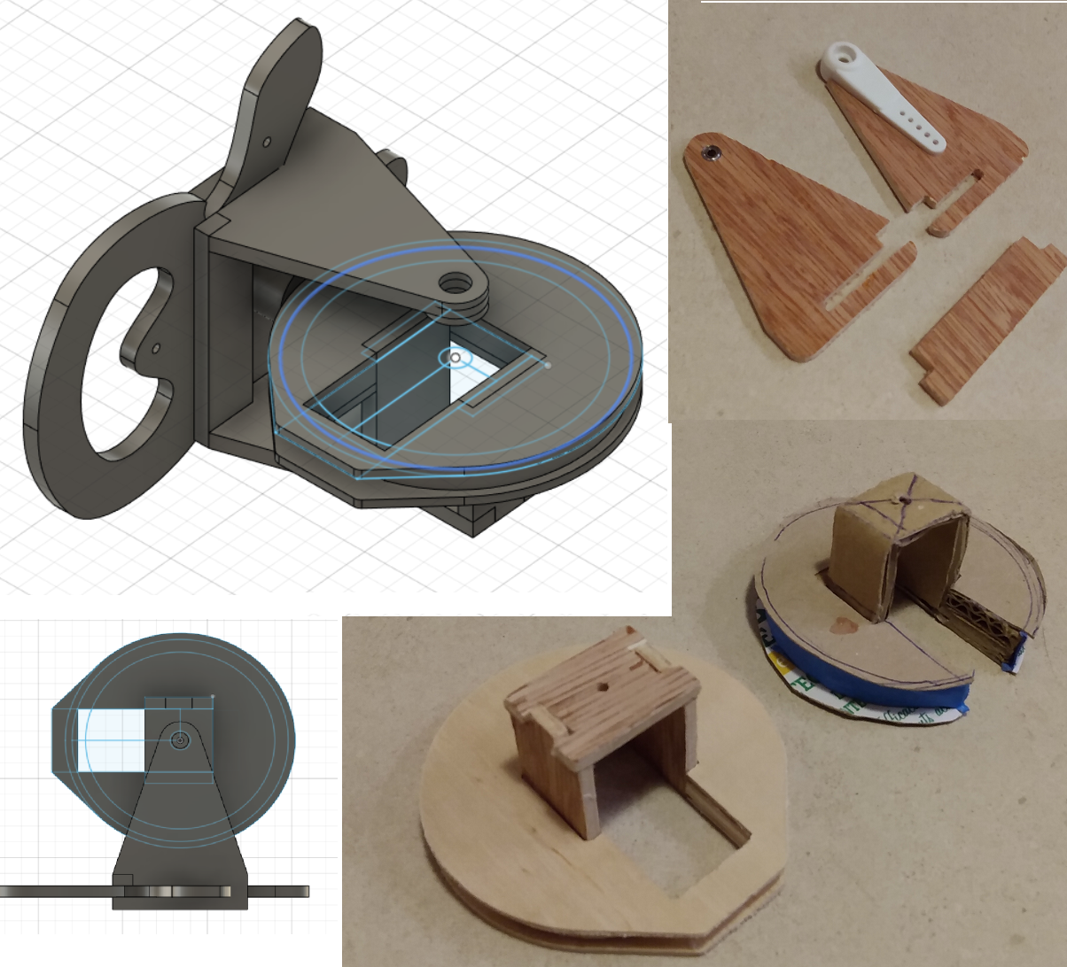
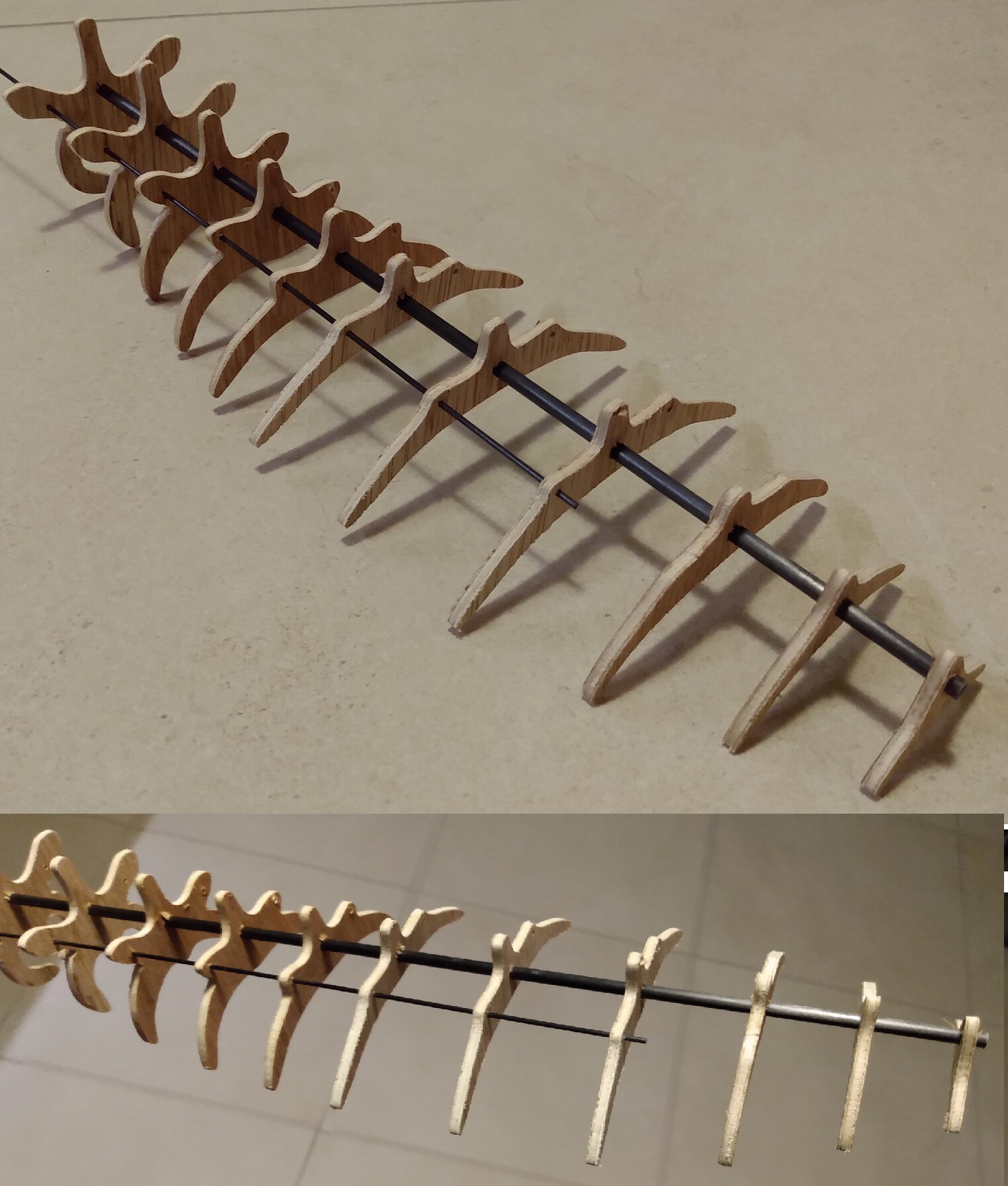 I think it'll be all right, i still need to figure out how i will link it to the arm... I'd like to have an adjustable articulation between the two to be able to shine the light away from my face if needed. Having this part ready will also help me figure out how much rigidity my arm requires: i bought several carbon rods (1 , 1.5mm and 2mm) and i'm confident that i can find a combination of those that will give the spine its stiffness...
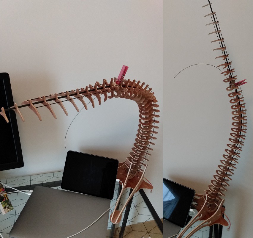
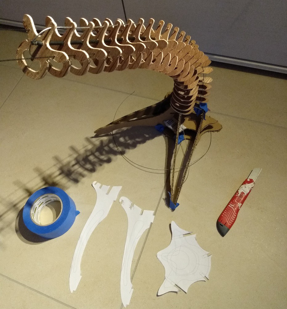 After a bit of tinkering and tape, i managed to get it standing !🤓
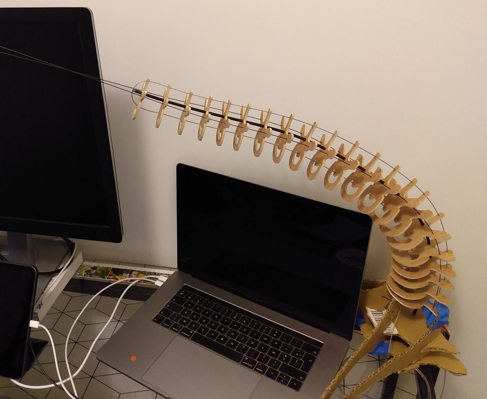 But the overall shape is a bit dissapointing : the stiffness of the central shaft being the same all along the arm, it has a tendency to bend a lot a the base and the final segment is relatively straight. No matter what tension i put on the cable , the bending will decrease toward the tip of the lamp .
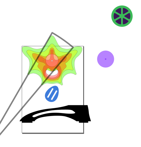
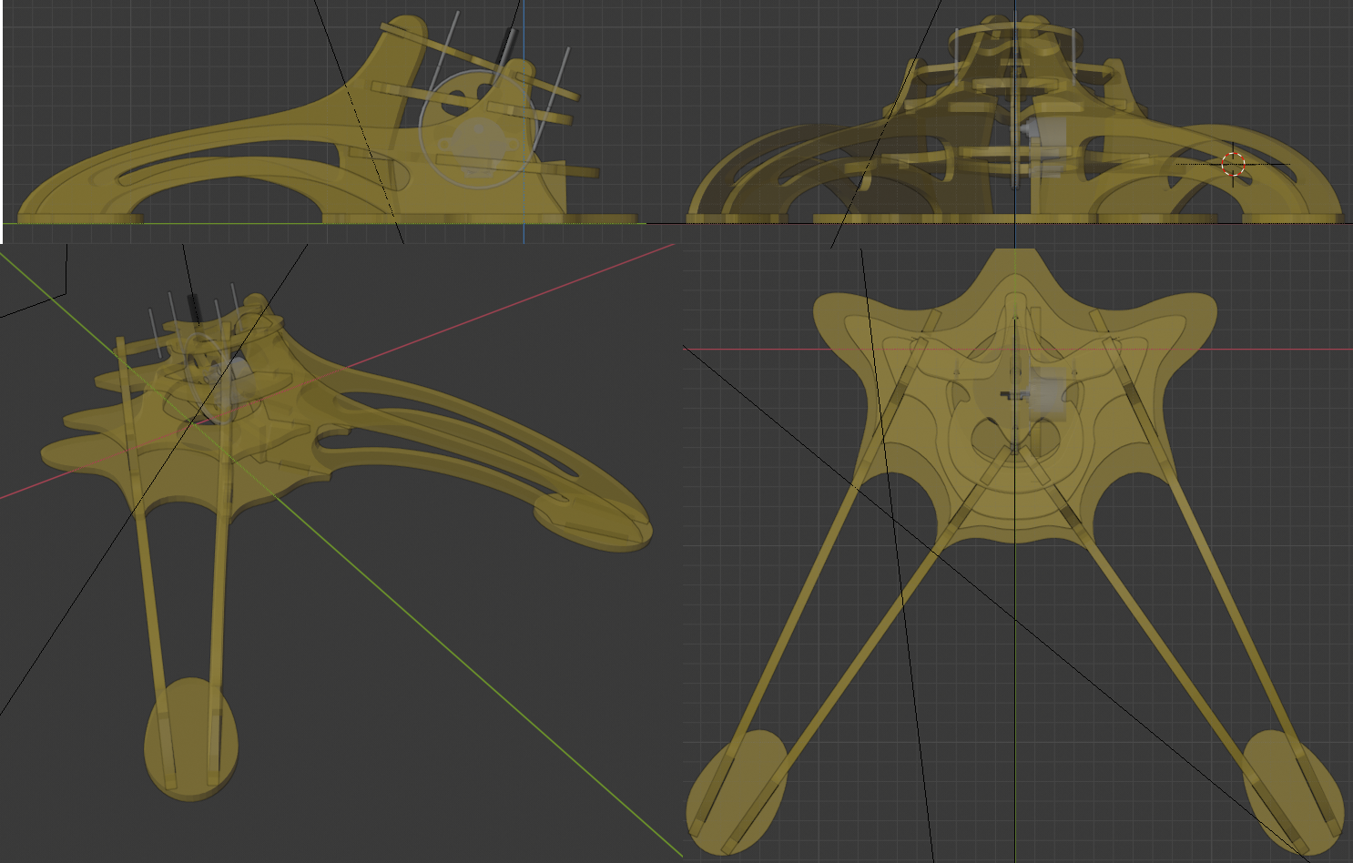
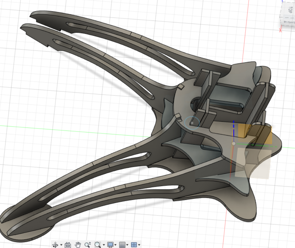
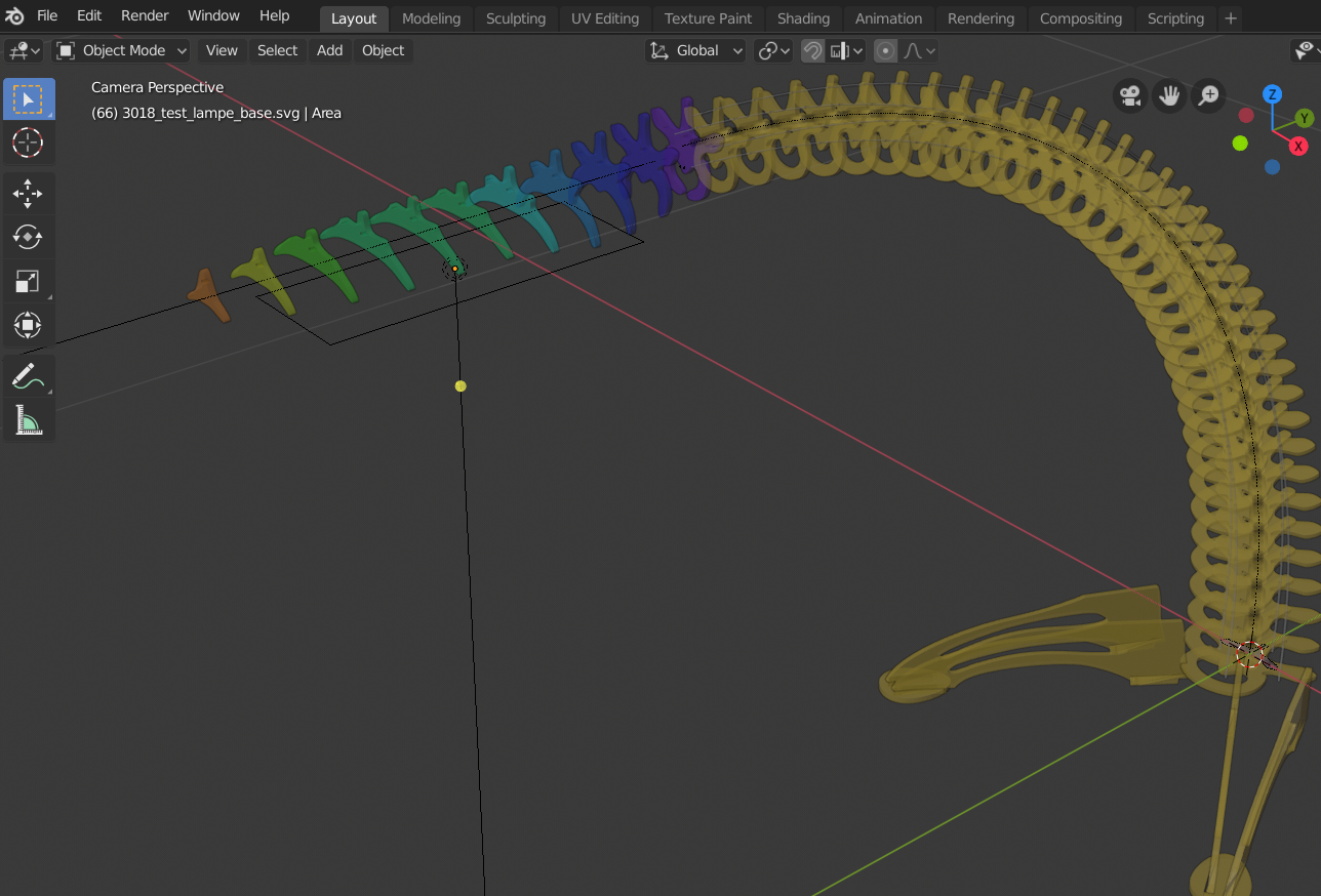
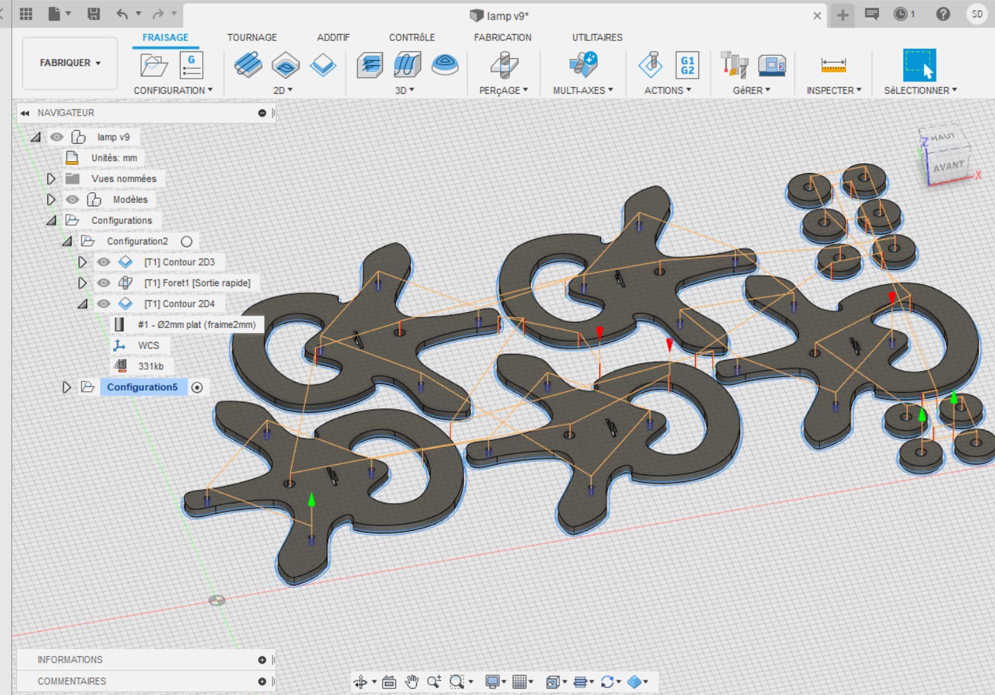
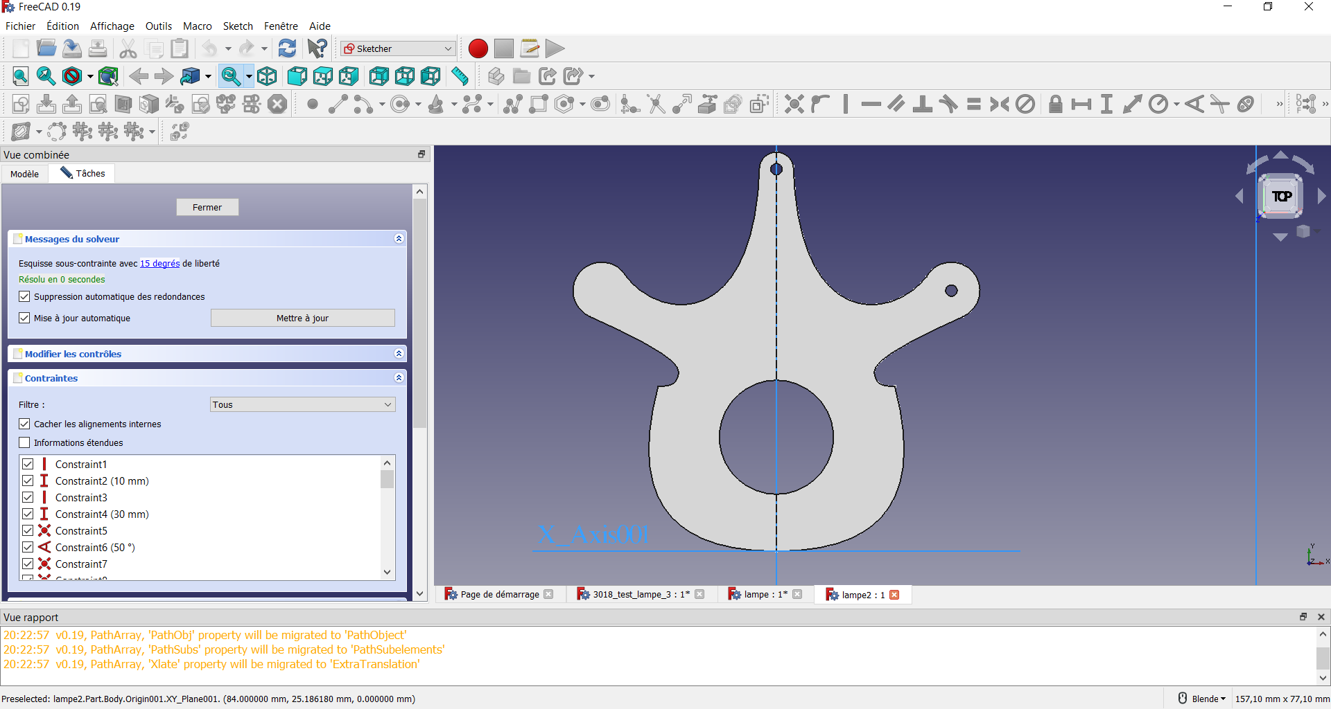
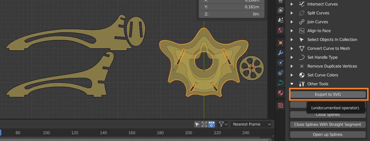 I used the duplicate linked feature which allows to clone a part and move/rotate it in place. When a modification occurs on one part, it is reported immediately on the other one: i have in a corner of my scene all the parts in a 2d plane that i'll be able to export at will. I don't know if fusion 360 or another cad soft can do that less painfully but i already know blender well so...
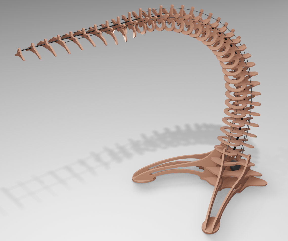
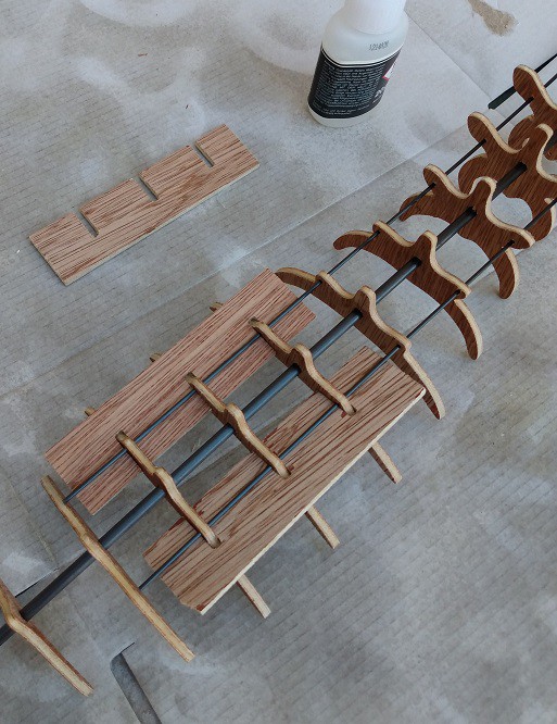
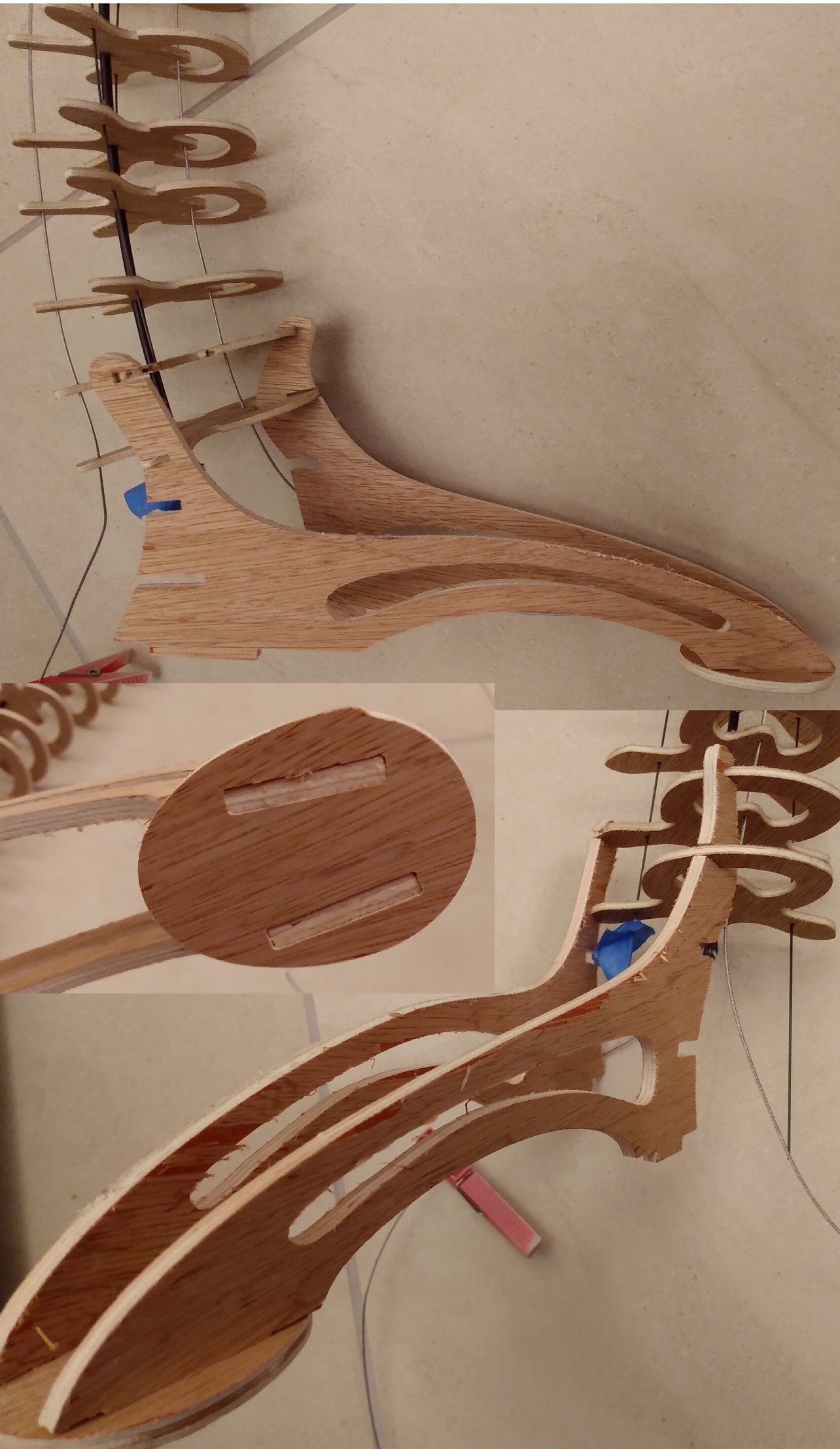
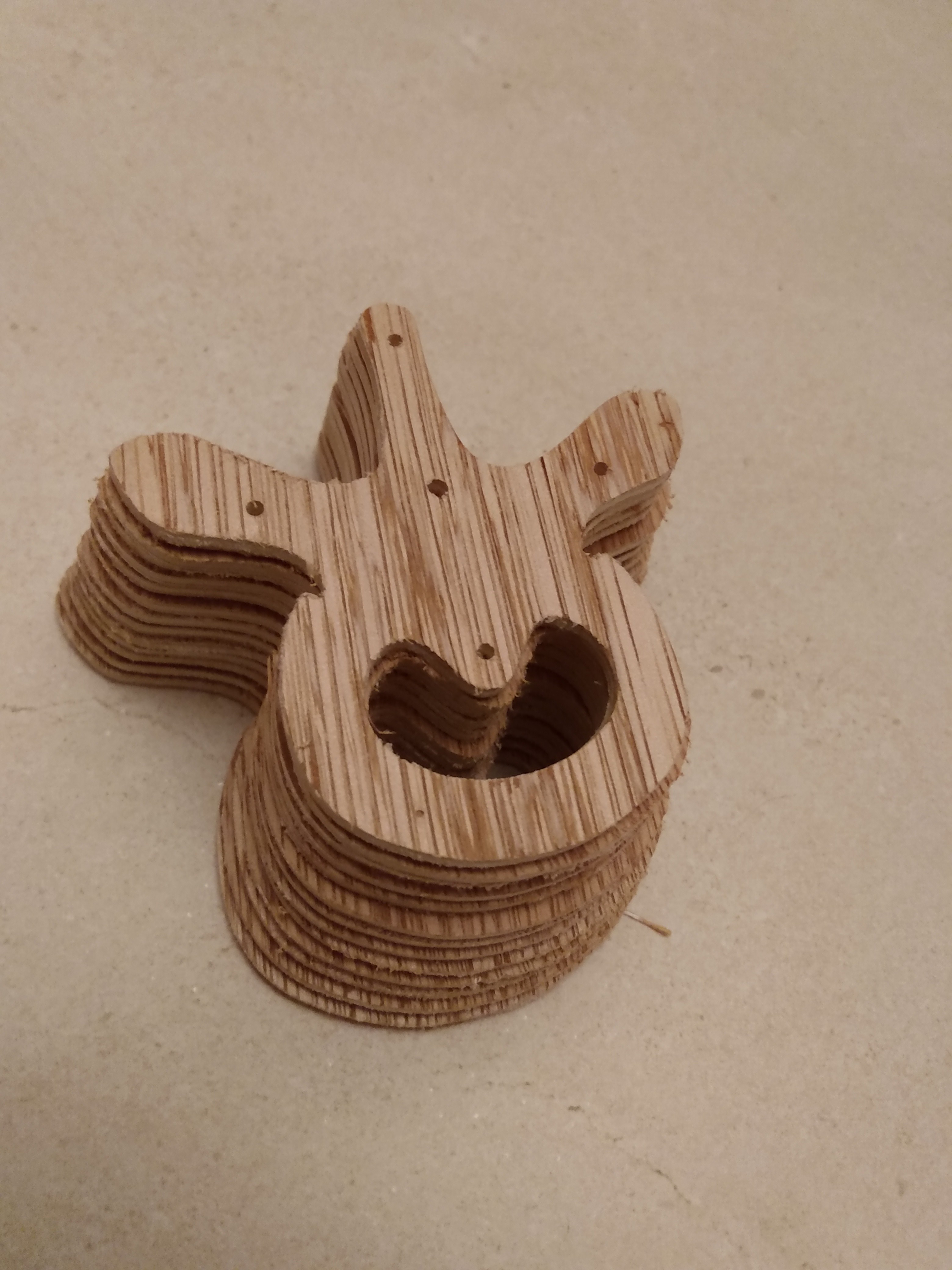
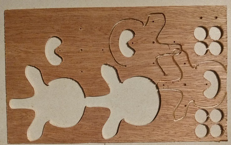
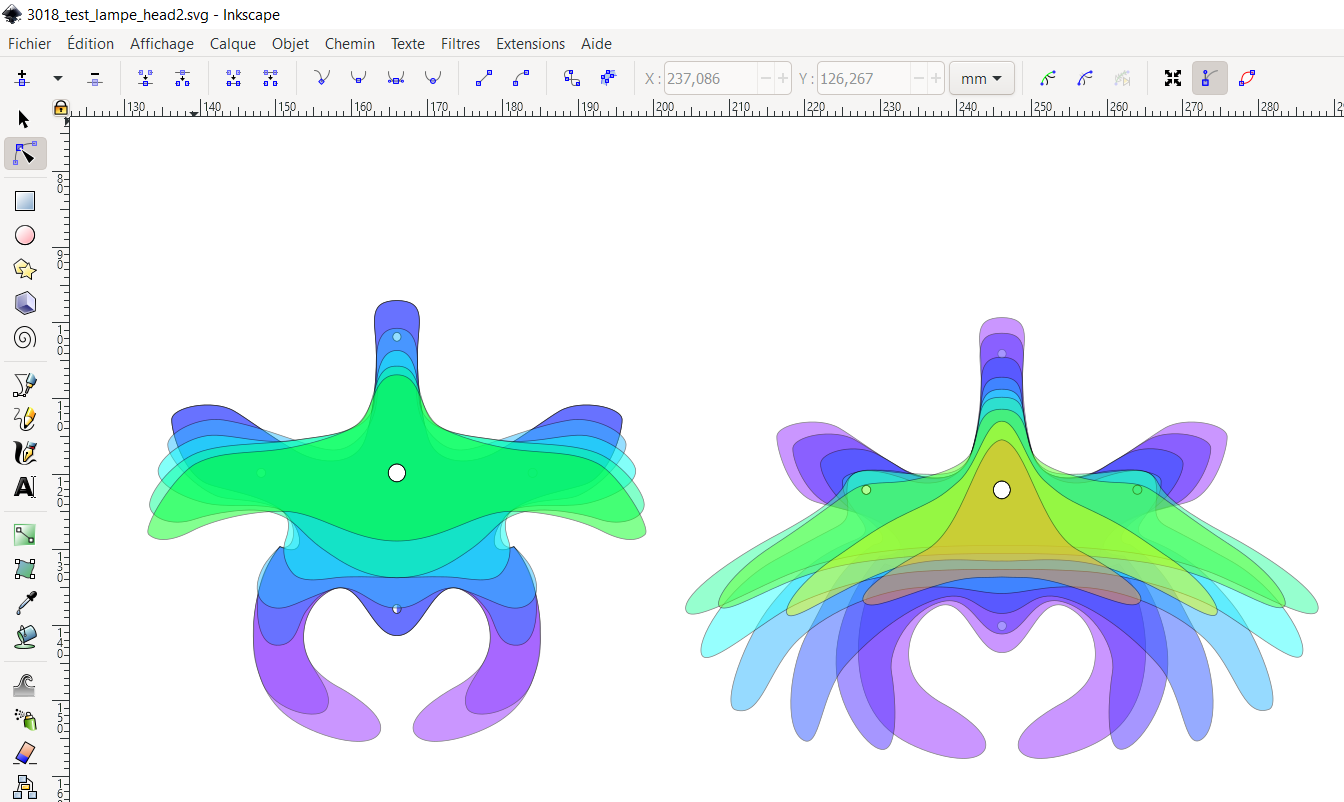 I'm pretty happy with this methodology: i use the center hole that will allow me to glue these parts on a carbon tube as a reference point. Then i can control and correct the morphing between shapes to smoothly evolve them into one another.
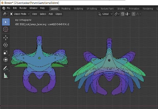
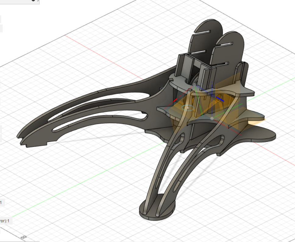
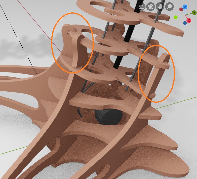
 I also started a foot design but i'm not sure how to link them elegantly to the base of the tentacle...
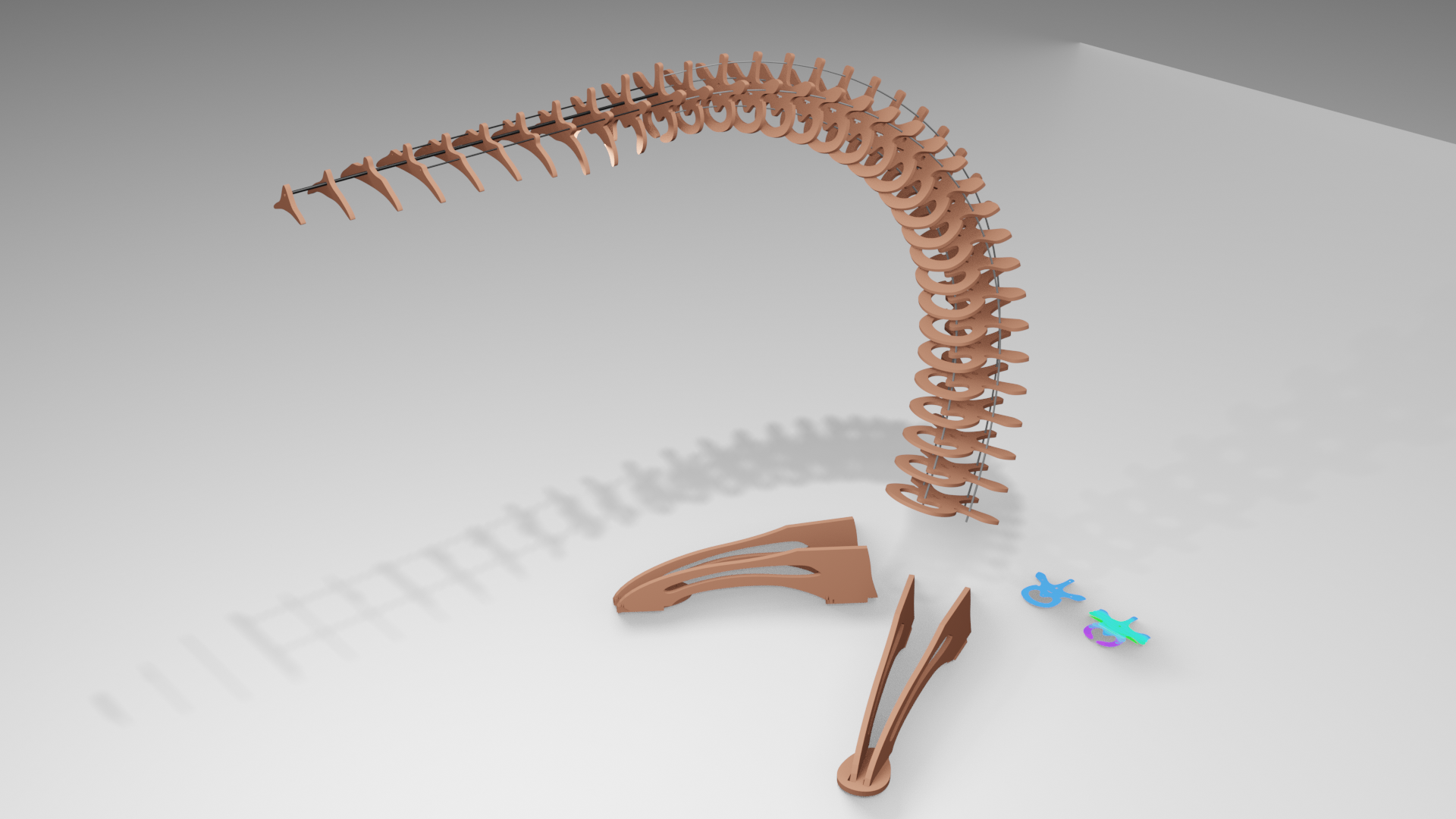
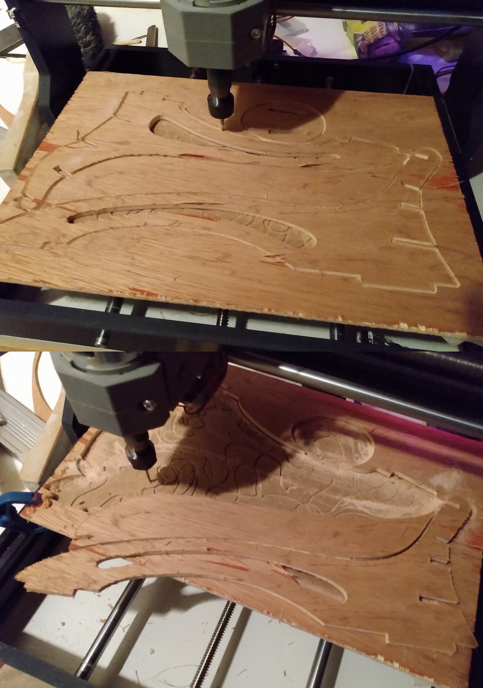
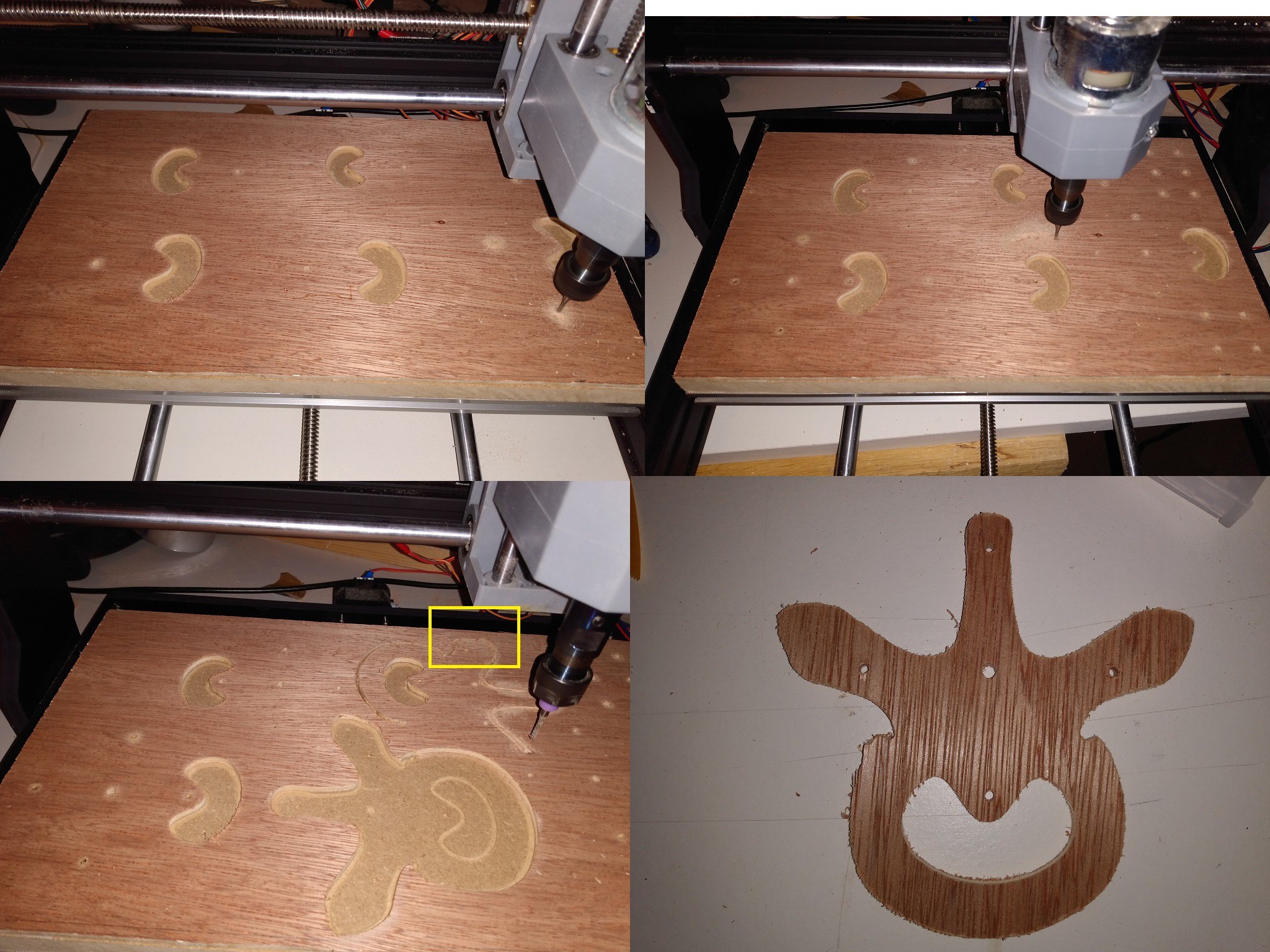
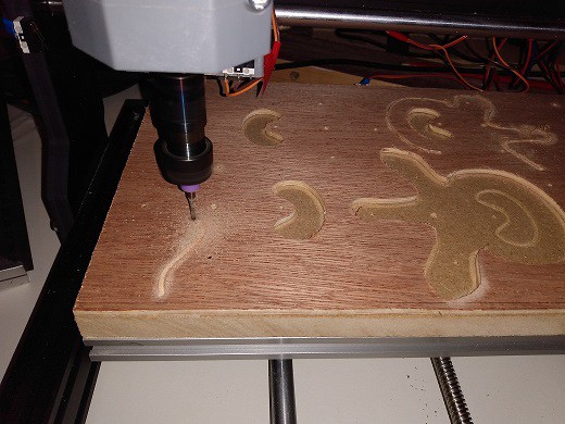
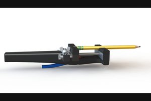
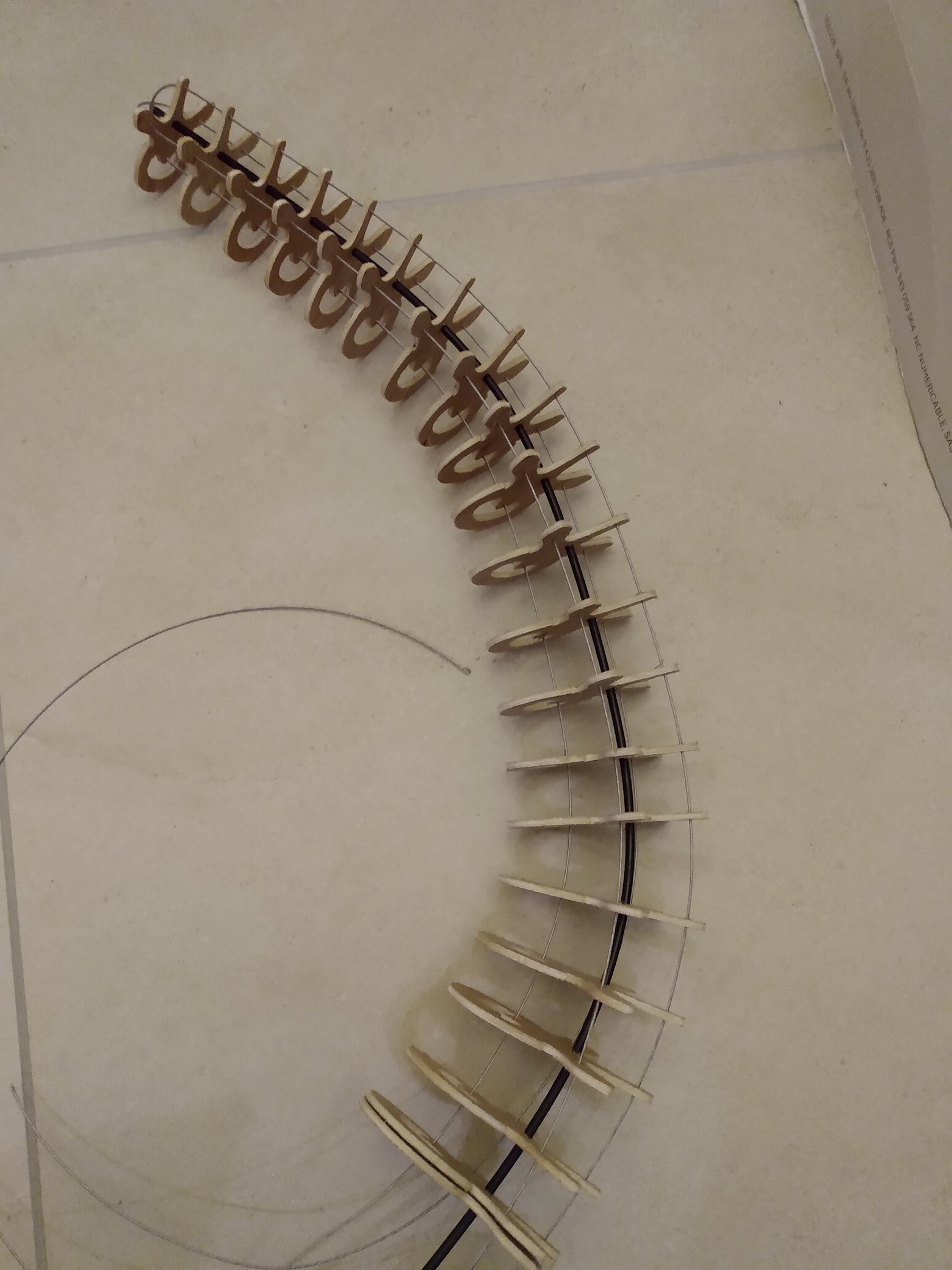 the only problem was that i had to re-drill every hole to make the bike shifter cable go though... I also understood why my plywood started to fell off : there is only a micron thick layer glued on every side! I though plywood was made of equally thick layers but this one is plated :( .
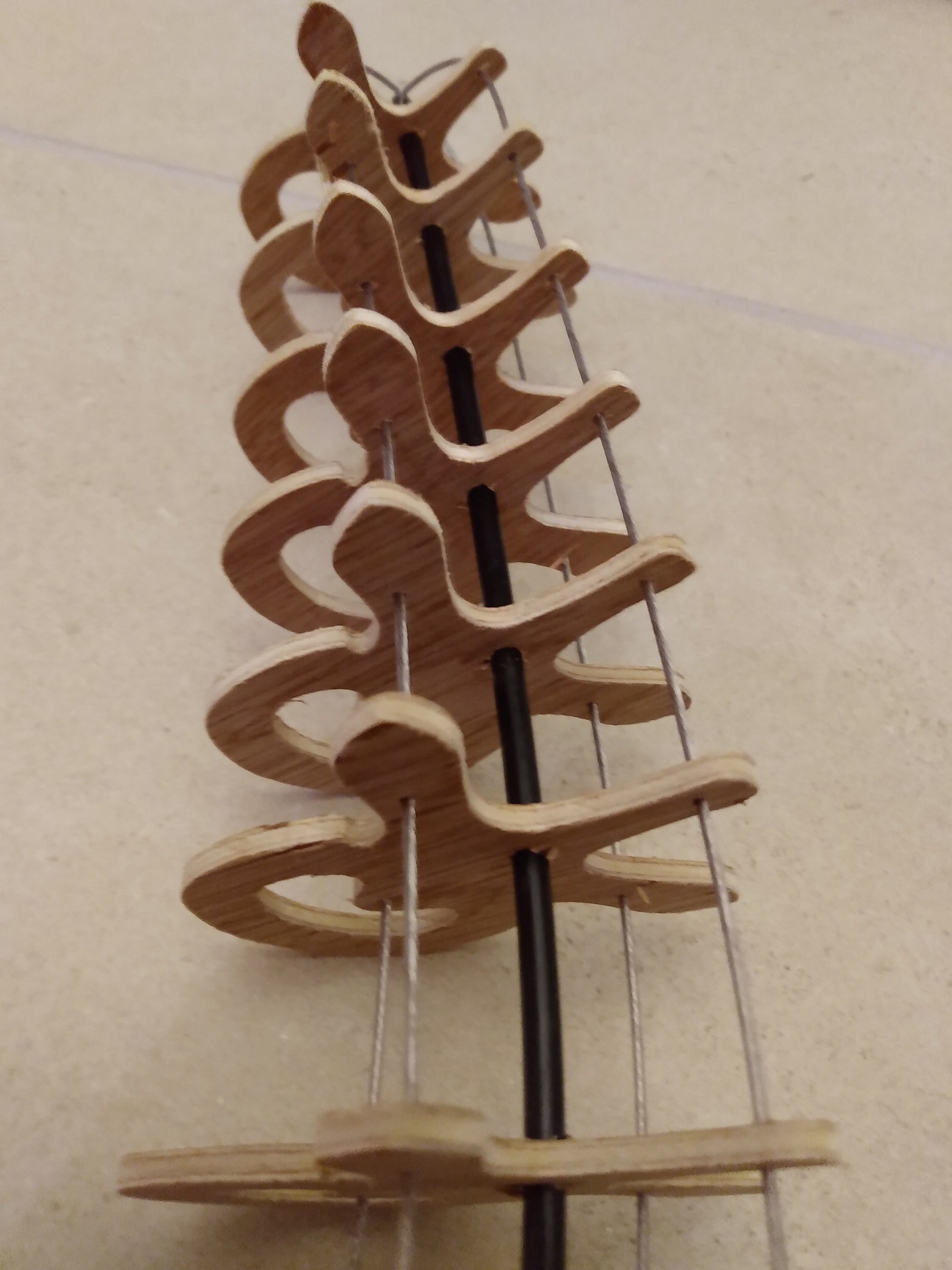 i used steel fishing line (rated 63kg, coated in plastic) for the actuation cables it looks lightweight and works well.
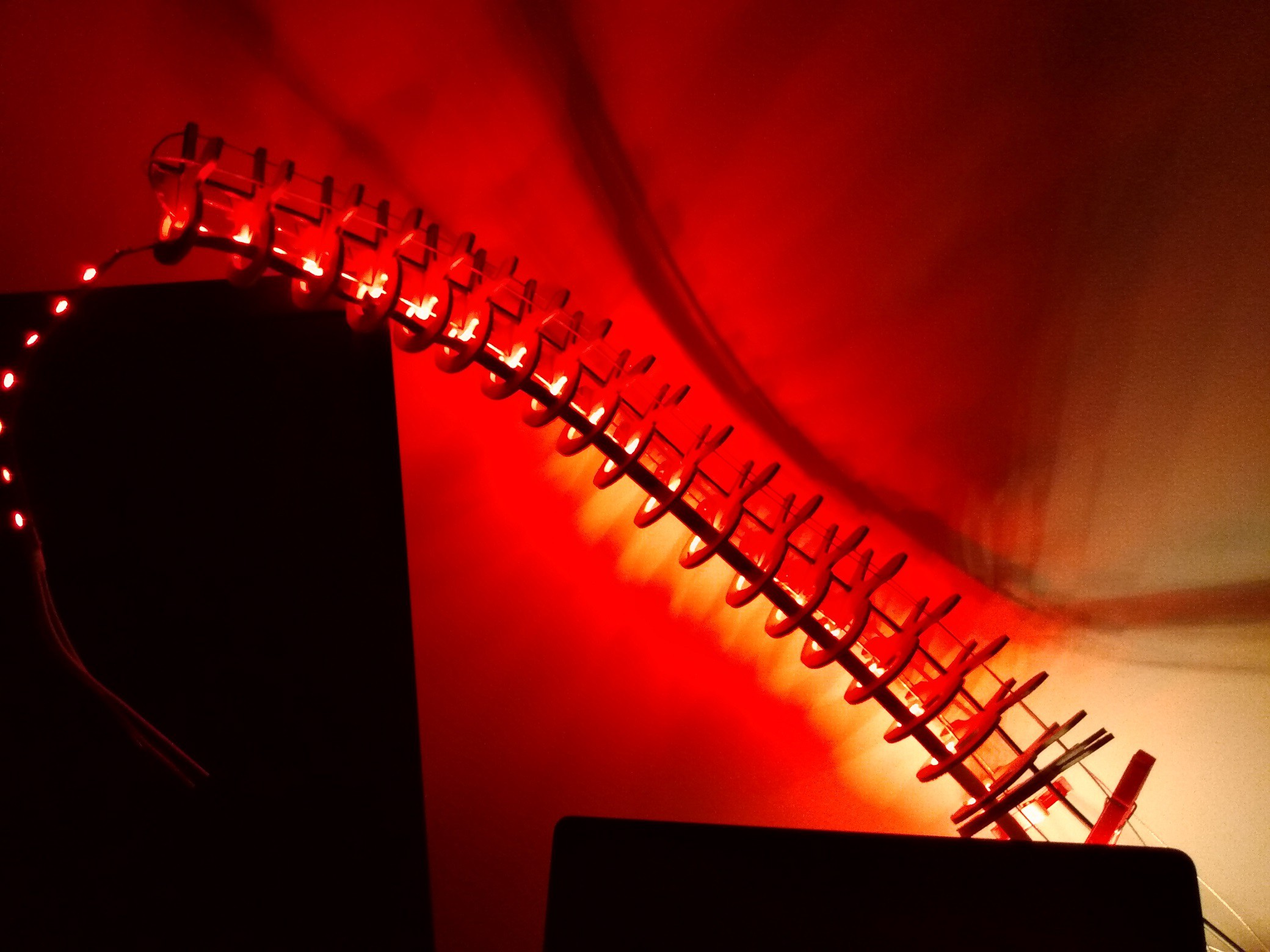 I don't know if it will make a great lamp but it is a really fun thing to build !
  I will look into what i can do to improve the movements predictability but for now i'm really happy on how it came out !


 Alex Rich
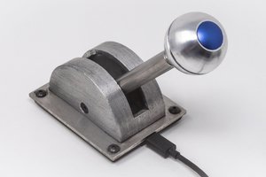
 zapwizard
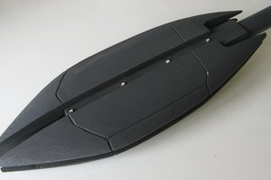
 shlonkin
Very nice project. I wonder if trying to add an stepper motor is holding the project back. Instead of fighting friction the better option might be using it. If the lamp keeps its shape while still being adjustable by hand may be even better. Adding a motor won't make the lamp easier to adjust than just moving the lamp head around. This will also solve you issue with the spine not bending at the right position. May be adding a bit more friction at some strategic points may be necessary to keep the shape on the full length.