 Juan Flores
Intro:
Back in February, I've received an ST7789 display module, the image and color quality was impressive despite the small size, so one idea comes to mind...
What if I build a keychain that you can play Pokemon?
At that moment born the primitive idea of microByte. After more than seven months of development, the idea of keychain evolved to a fully functional hand-held console that can emulate:
- NES.
- GameBoy
- GameBoy Color
- Sega Master System
- GameGear
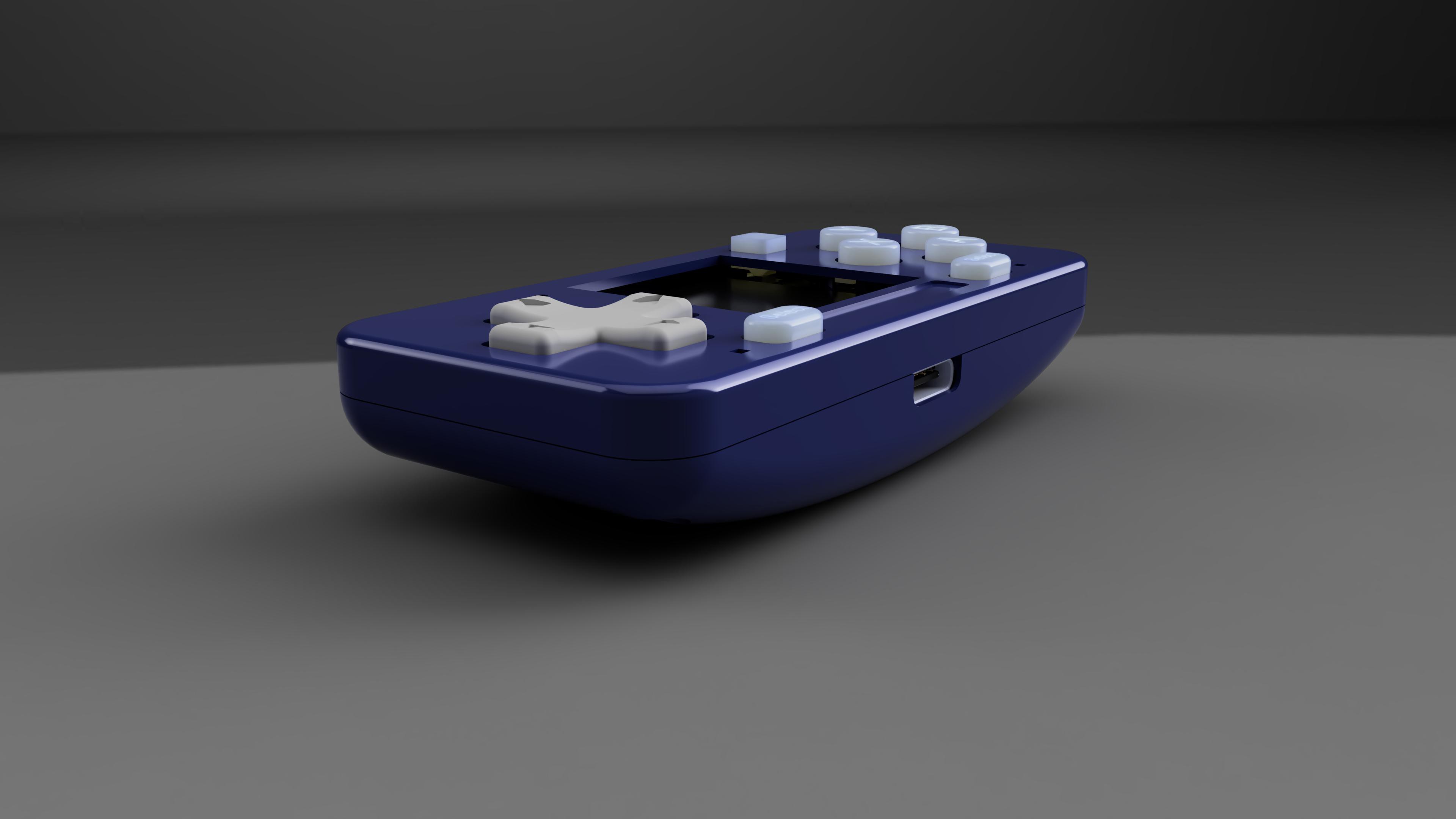
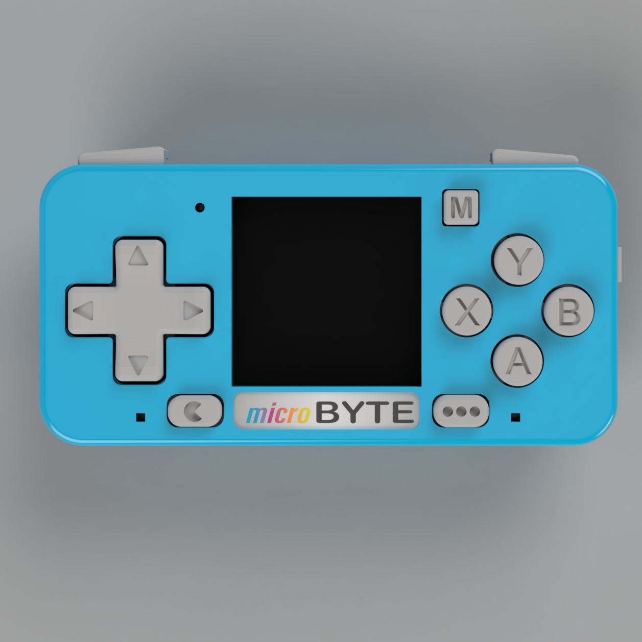
All of this in an inferior size to an original GameBoy cartridge and most important you can perfectly read the texts on the game. The dimensions are: 78x17x40 mm

(The image quality is better on the reality, but it's difficult to capture with the camera)
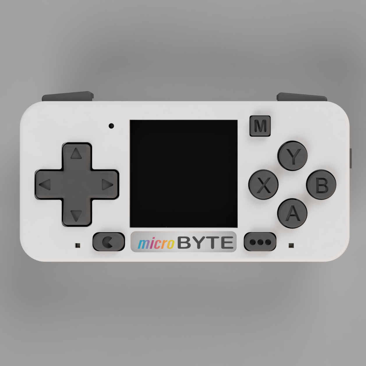
On the other hand, you might wonder why add SNES gamepad layout (Direction buttons, 4 action buttons, Start, Select, L, and R trigger.) if it only able to emulate 8Bit games?
Well, yes at this moment it's only able to run 8Bit games, but doing a deep search I've found that there are some early ports of SNES emulator and SCRUMV to the ESP32. So, it was clear, this device needs a full SNES gamepad layout with future updates in mind.
Finally, apart from gaming, I think that this device can be a very useful tool to develop ESP32 projects, because you can run Arduino Sketch and/or ESP-IDF project binary from the SD Card like an "App", without deleting the main firmware. I will give more details on further points.
Here you can find a video summary.
SPECS:
I'm going to split the specifications of the device into hardware and software to give more details of each one.
HARDWARE
First, we will start with a general list of hardware characteristics:
- ESP32 WROVER E (16MB)
- 8MB of RAM
- 16MB of flash
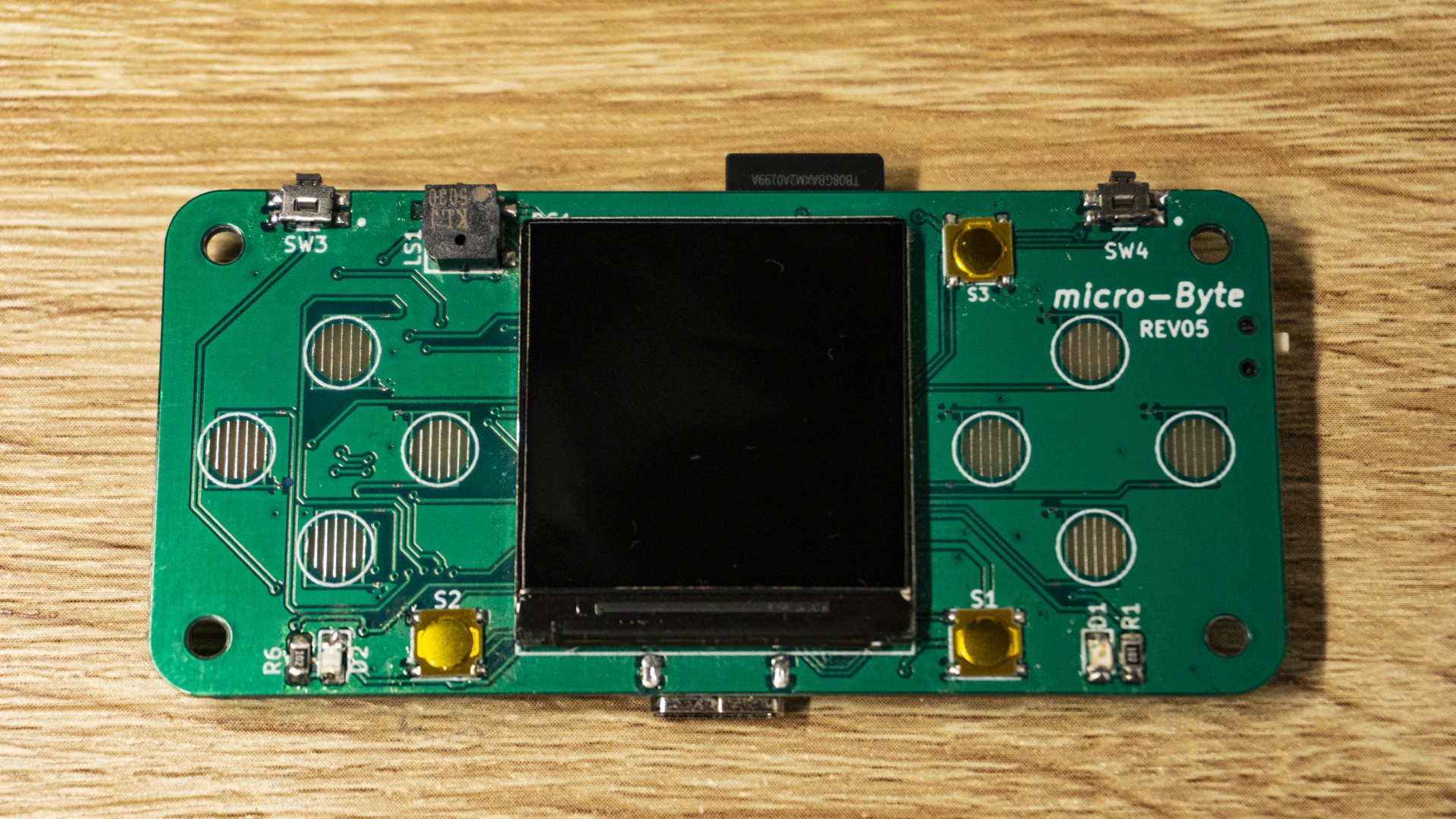
- ST7789 IPS 1.3" display with a resolution of 240x240 pixels
- micro-SD card slot.
- On-Board speaker with MAX98357AETE+T I2S audio amplifier.
- 13 onboard buttons connected to TCA9555RTWR mux.
- 8 Inductive buttons with a rubber membrane. (Direction and action buttons)
- 3 done switch buttons. (Start, Select, and Menu)
- 2 horizontal switch button. (Left and Right trigger).
- Charge protection battery circuit.
- 500mAh battery (This gives an autonomy of 6/7 hours playing).
- USB-C connector.
In the next repo you can find a KiCad Project with the schematics and PCB design of the microByte project:
Some photos of the board:
TOP View
BOTTOM View
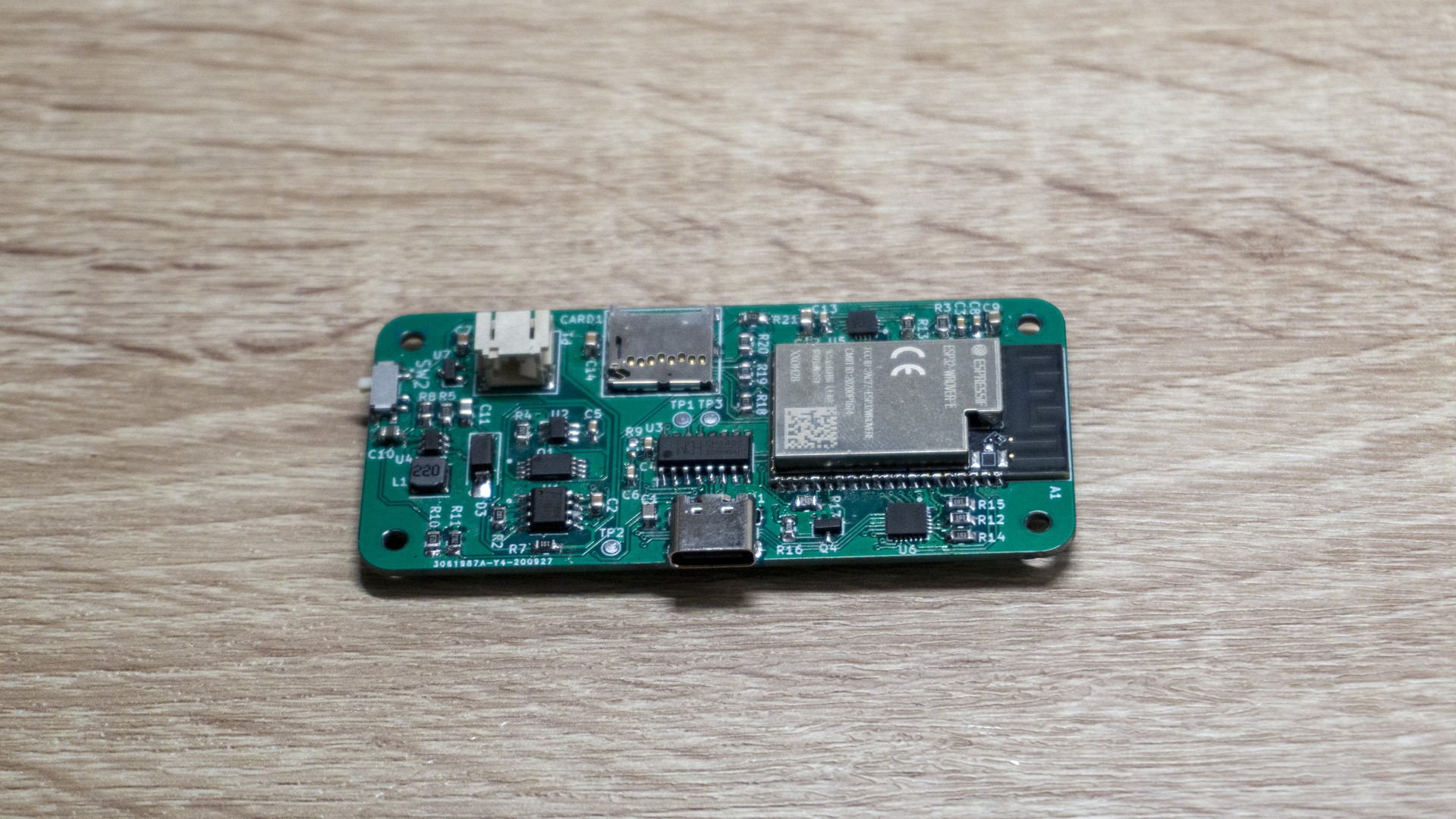
I was thinking to give headphones support through the USB-C connector, but I discarded by now the idea, because, I didn't find too much information on an implementation standard. It looks that each manufacturer implements differently the audio through USB-C. So in this PCB version, the connector only works to charge the device and connect to the serial console and see the debug log.
As you can see in the second photo, I use a standard PH 2.0 connector, to attach the battery. This gives you the chance to use a higher capacity battery. If you want to use a lower capacity, it's important to change the resistor R2 to use an appropriate value. This resistor sets the current charge configuration for the TP4056 chip. If you don't change the value of the R2 resistor, it could produce damage to the Li-Po battery. Finally, regarding the power management, the device has a step-up converter which warranty a constant 3.3v output, this solution avoid dimming on the screen and unstable behavior when the battery is dying.
The audio amplifier is a MAX98357AETE+T. This driver transforms from I2S to ADC, it can be configured to work with mono/stereo sound and the gain is configurable. I set by default at 9dB of gain. I think that it's fine to avoid damage to the speaker. Regarding the speaker, it's very difficult to find an affordable SMD speaker that can fit the PCB space, so I've found a buzzer with a good frequency range, which fit properly the PCB size.
The audio quality is not the best, some audio tones are lost, but I'm generally the sound quality is pretty decent. You can see it in the first photo of the PCB.
Finally, I must say again that the screen is awesome for the size and price. The image quality is awesome. But the other thing that I was pretty impressive, it was possible to achieve stable 60 MHZ communication speed, using basic SPI (I mean, no quad-SPI).
SOFTWARE
The software was developed using the ESP-IDF framework and freeRTOS as RTOS.
You can find the firmware here and the explanation of how to set-up here:
The design was focus on achieving a modular architecture. This modularity allows adding or/and modify new software features such as new emulators.
The entire architecture is controlled by a manager task, this task checks the battery level, the LED notifications, check the updates and control the GUI and emulators tasks, pausing or resuming it depending on what happens.
At the bottom software layer, we have the HAL(Hardware abstraction layer), which simplifies the access to the hardware resources by the emulators, manager task, or the GUI. Finally, at the very bottom, we have the drivers who interact with the HAL.
All of the emulators and the GUI runs on the same ESP32 app, this returns a very good load time of the games and general of the system. The games with a size inferior to 4 MB can load in less than two seconds!
The GUI is designed with the LVGL library. This is an open-source library which allows creating a very nice and modern looking graphical user interface. The GUI for this project tries to be simplistic but full of options. I'm trying to add a nice configuration menu that allows you to configure the behavior of each emulator and the device related options.
At this moment, it only allows the next options:
- Modify brightness.
- Modify the volume level.
- Change interface color.
- Set dark mode.
- Get device data.
- Get SD card data.
- Get battery data.
Another important point of the device is the emulators. The included emulators have been improved and adapted to the device. The GameBoy/GameBoy Color and Game Gear emulation get very good results allowing full frame rate.
Finally, the external application feature is like a "trick" but with very good results. This device has two OTA partitions, any of them is the main partition. I mean, if you have the "version 1.0" of the firmware flashed on the OTA 0 partition and you want to update the device with the "version 1.1" via SD card, the next reset if the update succeeds, the main app partition will be the OTA 1 running "version1.1" and the OTA0 partition will be erased.
So to load external binaries without losing the main microByte firmware, we are flashing a binary to the free OTA partition but without sending the confirmation signal to the device, this will cause that when you reset the device, the OTA partition with the application will be erased, because for the device is a failed update.
This is a quite fast process but has a huge dependency on the binary size. For example load, a simple Blink example could take 5~10 seconds, load Doom 1 game up to 20 seconds.
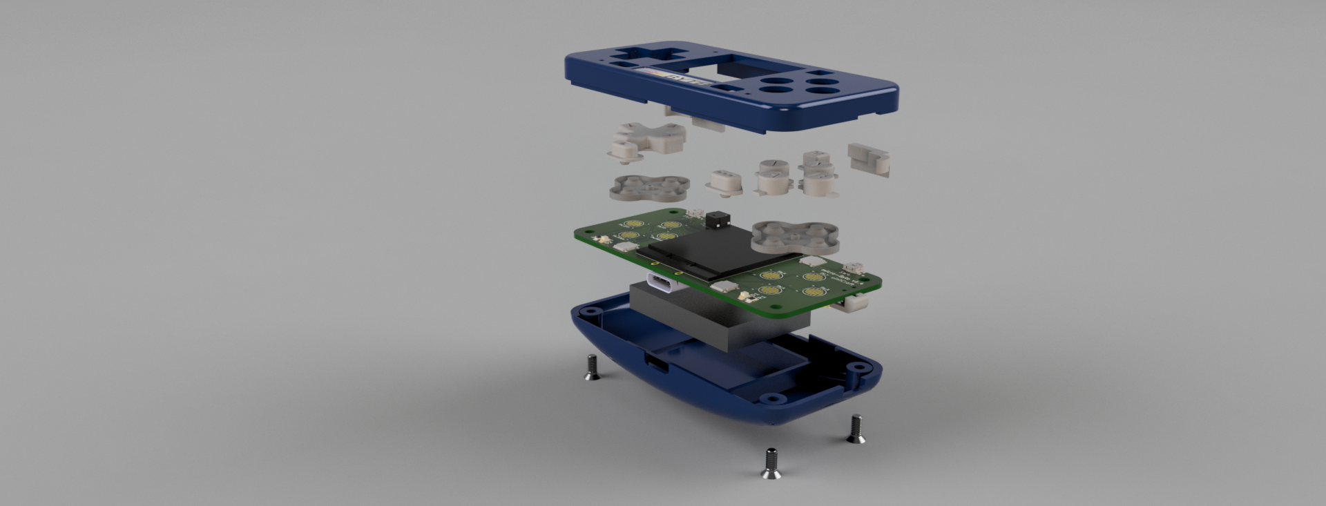
DEVICE CASE:
The case is designed to be easy to print with a 3D printer but also to be comfortable playing. You can find all the files on the next repository:
On the other hand, spend a lot of hours thinking about which kind of buttons could fit best, I realize that it was a must to add a rubber membrane to have a good "click" sensation. On the other hand, I've tested some of the newest portable console available on the market, and I realized that it has the perfect size for a little modular gamepad, so I thought that it was to be inspired.
As I mentioned before, the case it's very easy to print, I've printed with PLA and PTEG on an Ender 3 with very good results. Also, I've printed a few on SLA printers like the Eleegoo Mars with also fantastic results.
I'll upload very soon to the reposotory the print instructions.
The assembly process is very easy, I'm doing a little video to show the assembly process, but you can see a basic diagram on the next image
Here I attached some renders of the case in different colors:

FUTURE IMPROVEMENTS:
At this moment the performance, in general, is stable and good, giving full frame rate on GameBoy/GameBoy Color and GameGear games.
But I think the main issues to solve are the next:
- Improve NES performance. Most of the games work fine, but some have some glitches and the performance is not stable.
- Improve the tearing effect. Some games have a noticeable tearing effect which is not a huge problem but can be uncomfortable to see.
- Little improvement on the GUI. The game has an in-game menu to manage the brightness of the screen, sound volume, save the game ... This menu sometimes is problematic and can block the hold system when is executed by pressing the menu button.
On the other hand, is planned the next add in future updates:
- SNES emulation support. It's still at a very early stage but I think that it could be possible to make it run.
- Add a repository with external applications such as:
- Bluetooth gamepad.
- Wi-Fi network analyzer.
- Doom.
- Create an Arduino library to create easily sketches for this device.
CREDITS:
GameBoy/GameBoy Color emulator is a port of GNUBoy emulator.
NES emulator is a port of Nofrendo emulator developed originaly by Espressif.
Sega Master System & Game Gear emulator is a port performed by Espressif.
Also worth to say that this project was inspired by ESPlay micro and Odroid GO, which are awesome devices.