External View.
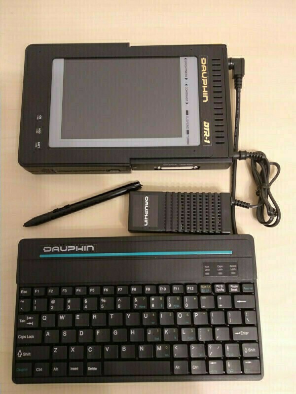
Today there will be a lot of photos. When taken from the leather box, the system with PSU, keyboard and pen looks like that:
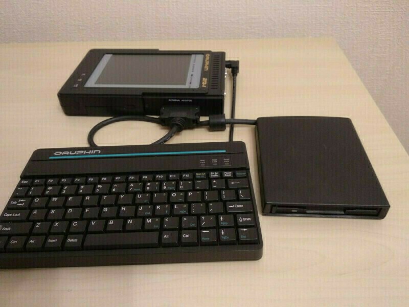
Floppy do not fit well into the photo with PSU, so here is another one, now with FDD and without PSU:
On the left side of the device there is 35mm wide battery compartment. It occupies the whole height of the system, that that's why left side has no connectors on it.
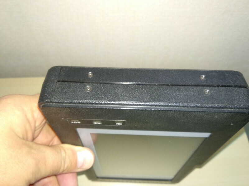
Three LEDs indicating the power state of the system (ON, green), disk access (HDD, yellow) and battery state (BATT, red). ON LED blinks, when system goes into suspend mode.
Battery cover and power slider switch located at the bottom side.
Connectors.
The system itself has connectors on the 3 of 4 sides.
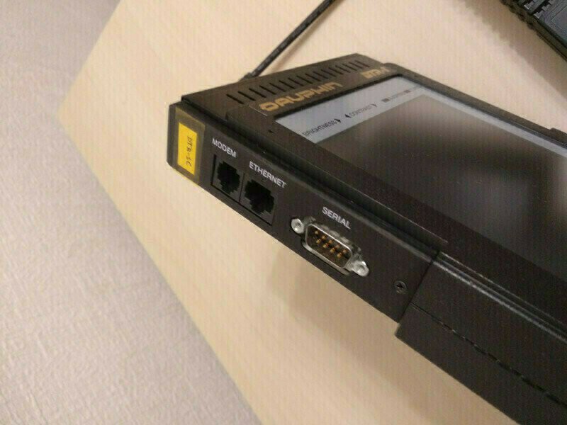
Communication connectors gathered on the top side of the case. COM1 routed to a DB-9M RS-232 connector with standard pinout, but COM port internally shared with Rockwell modem. As the PIO chip implements 16450 UARTs, 38400 will be the maximal speed of serial port.
Sharing COM1 between modem and connector means that only one device can be used at once. Switching are done by a pair of small DOS programs, they simply put different values into one of IO registers, possibly driving GPIO pin. I'll investigate it later. Modem connector is placed nearby and use a RJ11 (6P4C) phone jack.
The last connector on the top side is RJ45 LAN 8P8C connector. Unfortunately, network speed is 10Mbit/s and connector only works when LAN mezzanine card are installed.
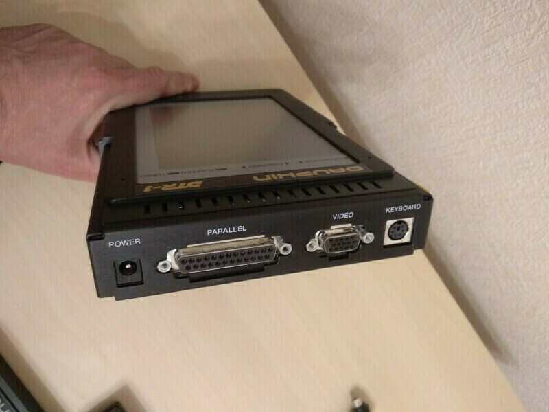
Right side gathers peripheral and power connectors. Power supplied by 2.5mm barrel connector, parallel and VGA ports has standard connectors and pinouts. Keyboard attached via mini-DIN6 PS/2 connector with standard pinout.
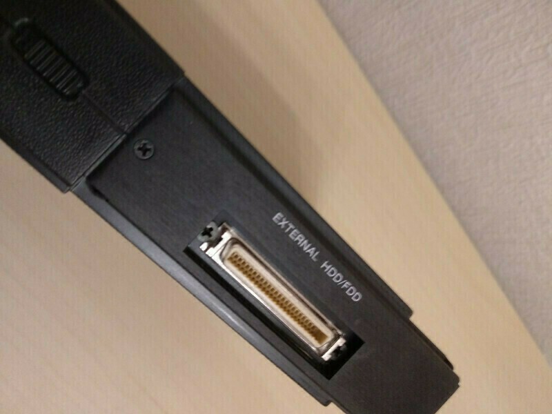 Custom FDD/HDD connector located with battery cover and power switch on the bottom side.
External HDD/FDD use high-density style 50pin connector, much like 68-pin connector
used for external LVD SCSI devices. Some pins shared between FDD and HDD and I suppose,
that connecting both at the same time may be impossible.
Custom FDD/HDD connector located with battery cover and power switch on the bottom side.
External HDD/FDD use high-density style 50pin connector, much like 68-pin connector
used for external LVD SCSI devices. Some pins shared between FDD and HDD and I suppose,
that connecting both at the same time may be impossible.HDD will be the slave device on the same primary controller. I do not own any DTR-1 HDD accessories, but will try to build adapter cable top 44Pin IDE if I can find HD50 plug for soldering.
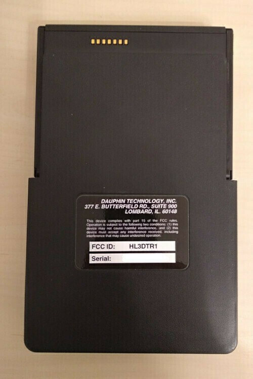
Back side do not have any interesting things except the 7 gold plated contacts. There were rumors about dockstation for the DTR-1. But the steel plate, that covers all connectors, the shape of the case and the 7 contacts makes me think, that some dock station maybe existed. While tracing the PCB I've found, that some of that contacts have a primary 12V power, so device can be powered (and charged) from the dockstation.
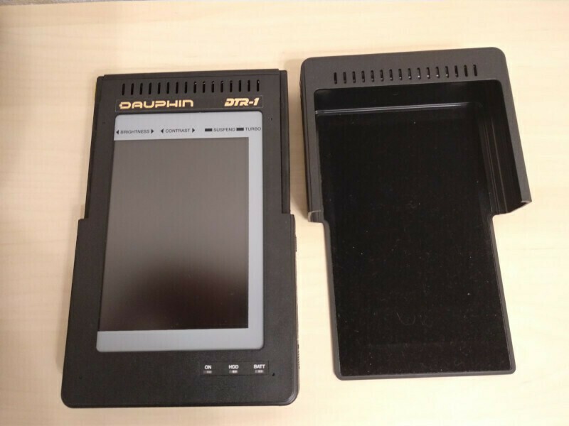
The additional plastic cover hides all connectors except keyboard and makes the device looks like a real tablet computer. Not as thin as today's devices, but still...
The design and location of connectors are not ideal, but they at least allow to use the tablet inside the leather case, while still connecting to power and network or phone line. Communication connectors are small, keyboard have 90-degree connector and PSU plus and cord just goes straight of the case on the lower right corner.
Situation is slightly worse with LPT and COM connected, and worst with VGA, that conflicts with angled PS/2 keyboard connector and with FDD, that have large plug and short and hard cable.
But all that usability stuff is unimportant. DTR-1 was a child of early 90x, when no microUSB, microHDMI, etc. yet exist.
Keyboard.
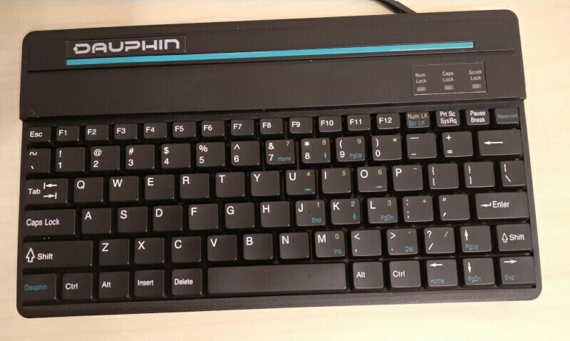
DTR-1 have a simple membrane keyboard. It has 90-degree PS/2 connector and short cable, both designed to fit with DTR-1 into leather case.
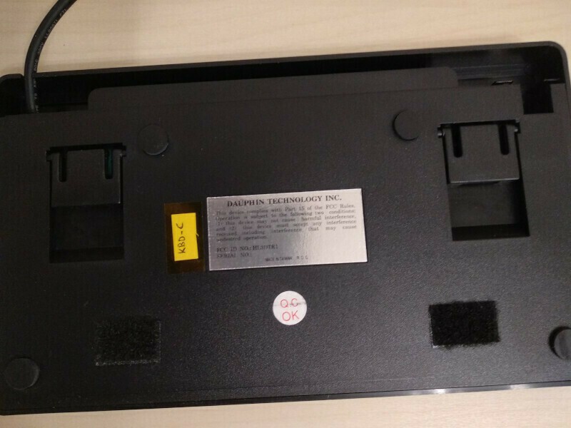
On the back side there are two stands, that helps to angle keyboard slightly and two Velcro pieces, that helps to fix keyboard inside the case. Case has another two pieces of Velcro tape glued to the same places - cheap, but workable solution.
Cable with connector may be moved to a compartment at the top of keyboard.
Keys are thin and have a simplified construction and often pressed with skew. Old plastic clips may break at any time. The last disaster with keyboard is degrading silver traces on the film. While my keyboards was not flooded, 25 years do not add them reliability. But DTR-1 should support any PS/2 keyboard, I even use AT 101 Key keyboard with DIN5 to miniDIN6 adapter cable.
Floppy drive.
Originally, I don't have a FDD. That's why any file exchange was a pain. Currently I have a couple of working FDDs and a thought to solder an adapter to ordinary 34pin FDD.
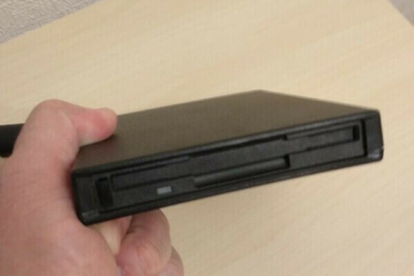
DTR-1 FDD internally use a slim 3.5" floppy drive, that sometimes were used in the laptops of that era. This drives use a flat linear motor for heads movement and also have 26-pin flat cable interface connector.
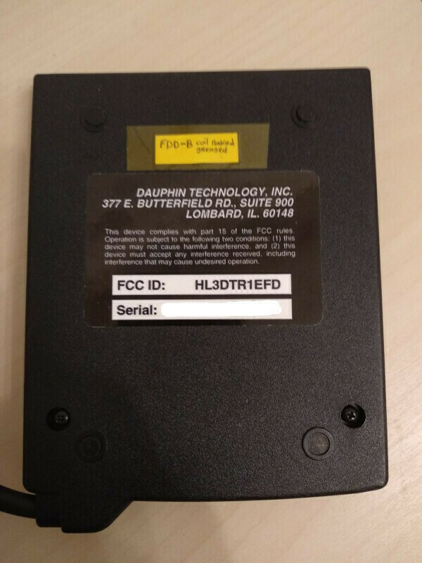
There is nothing interesting on the back side of the FDD.
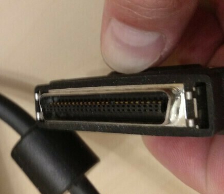
The plug is quite large, but fixes well with its clips.
Case disassembly.
Case consists of two parts - front and back. Front part contains display and touchscreen assembly, the back part holds motherboard with mezzanine cards and connectors, and the battery compartment. Four tiny screws (~M2x2) fix the front and back parts of the case together in the left side:
Special U-shaped steel plate used to fix case parts on the right side:
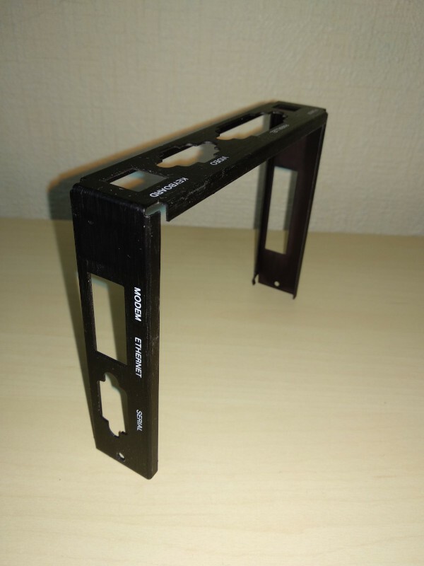
Plate have holes for the connectors and embraces both case parts not only at the right side, but partially at the top and bottom also. Two screws fix the plate at the top and at the bottom. As the result, the overall construction is tight and hard. The same plate used as a guardrail for tablet cover and the dockstation.
Power considerations.
There are no power characteristics printed on the device, but device uses 12V power, provided by standard barrel style connector with 2.5mm (or 2.1mm?) internal diameter. Voltage plus (+) connected to the pin contact and ground (-) to the barrel (outer) contact.
Original PSU was unreliable and overheat quickly. Now the situation is simpler, as external 12V switching PSUs used very widely to power low-end notebooks, LCD monitors, etc. I use PSUs rated at 12V@3Amps (36W) and 5Amp, for example ASUS ADP-36EH-C.
Next time we dig inside DTR-1...
Discussions
Become a Hackaday.io Member
Create an account to leave a comment. Already have an account? Log In.