What's inside
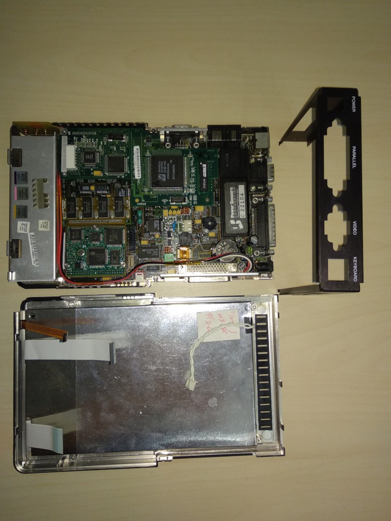
After unscrewing the case, we're get two parts: front part holds LCD, front panel LEDs and inductive touchscreen.
Back part holds all other devices of DTR-1 - mainboard with battery compartment and various mezzanines.
This is the overview of the internals:
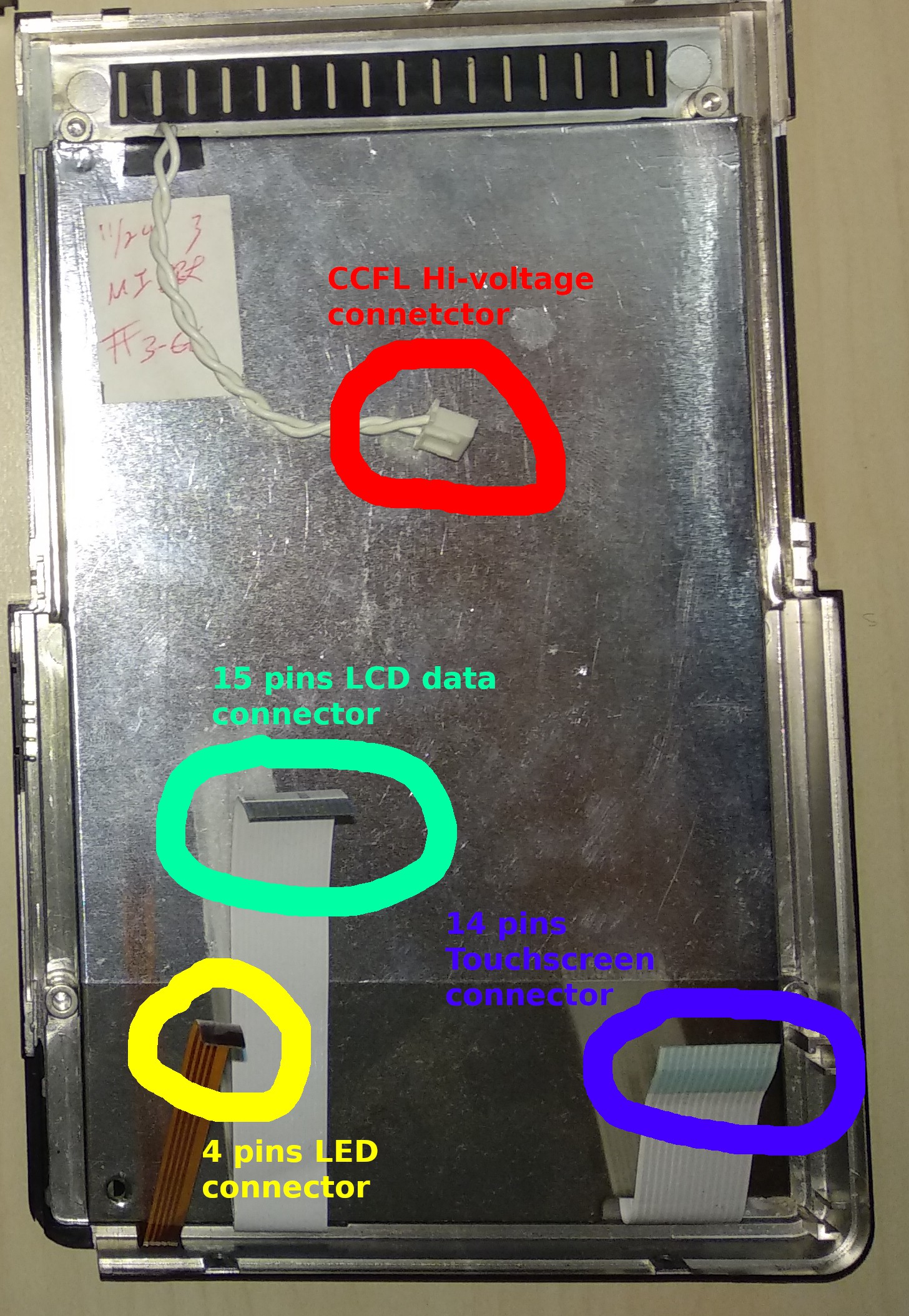
Top part has 4 connectors: hi-voltage CCFL back light connector, front panel LEDs connector, touchscreen connector and 15 pins LCD data connector:
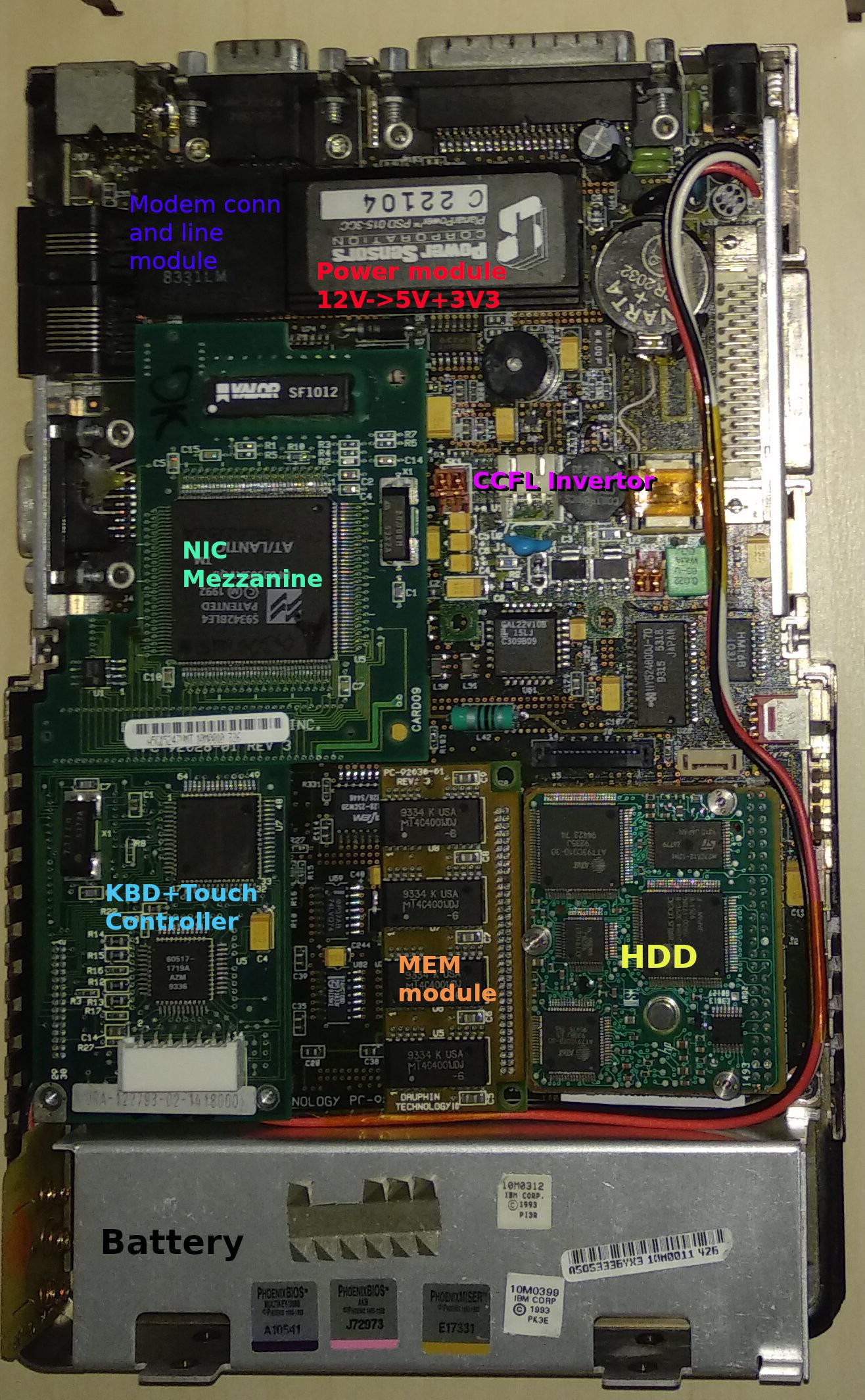
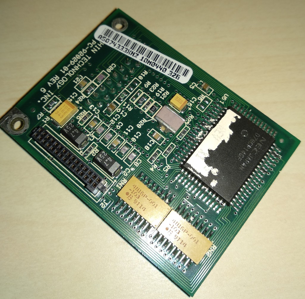
Motherboard carry some components as mezzanine cards: CCFL inverter, keyboard+touchscreen controller, memory module and NIC card (optional). Phone line for modem are connected through the Cermetek's CH1817 module, secondary power are also generated by monolith module by Power Sensors Corp. PlanarPower(tm) PSD 015-3CC.
HDD
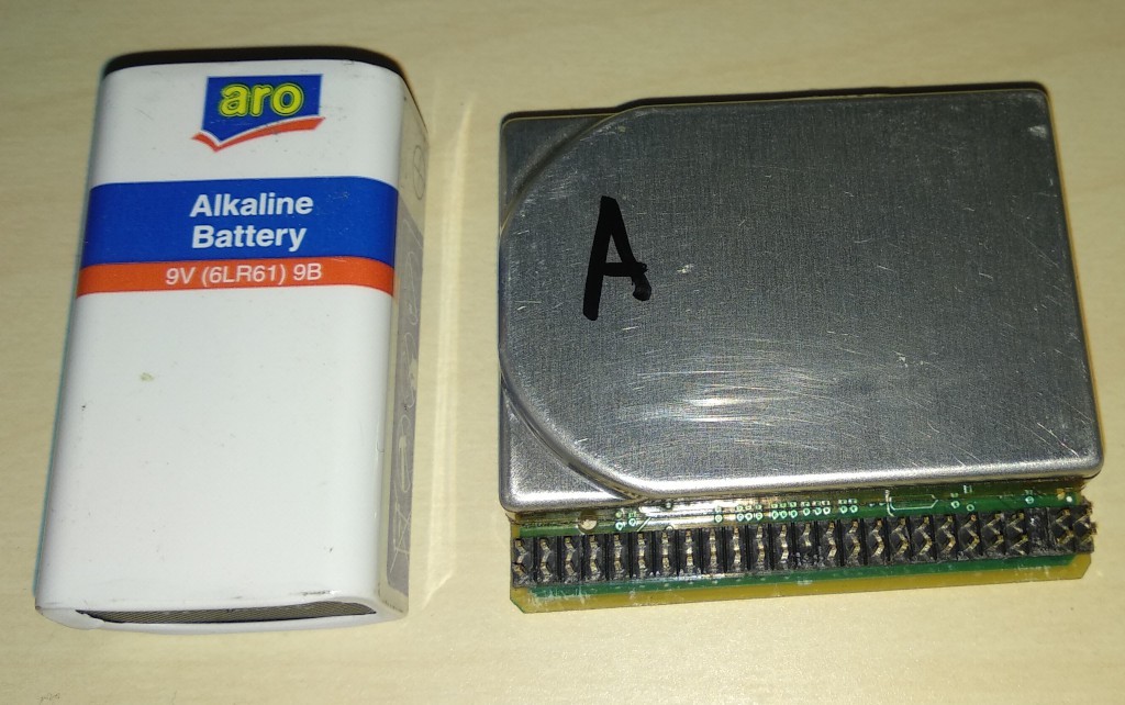
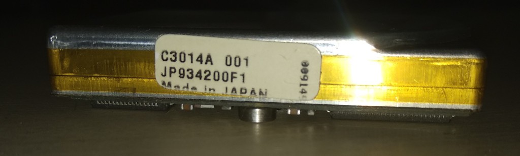
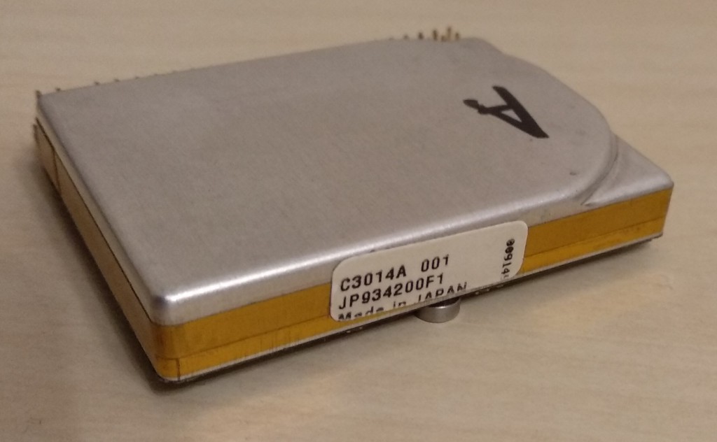
DTR-1 has a 40Mb HP KittyHawk drive, some older machines may have 20Mb drive from the same series.
While KittyHawk is not as famous as IBM's Microdrive, it is clearly an unique piece of art:
I do not know other drives that can have the same physical size and connector placement and that makes very difficult to upgrade or replace HDD in DTR-1. But modern tech brings the alternate solution: there are cheap microSD/SD-to-IDE44 adapters that can fit the existing DTR-1 HDD compartment.
They need to resolder connector to be at 90 degrees and cut PCB by ~2mm. I'll write a separate article about it later.
 KittyHawk drive supports PIO modes only and do not support LBA. Moreover, LBA is not supported by BIOS code, so there may be problems with implicit translations, for example Linux's LILO do not work as the CHS-LBA translation done by LILO do not match the addressing, that BIOS can support.
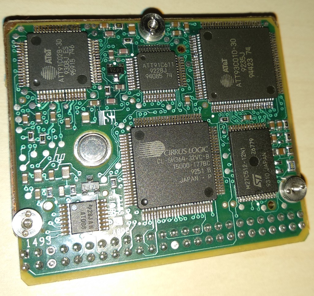
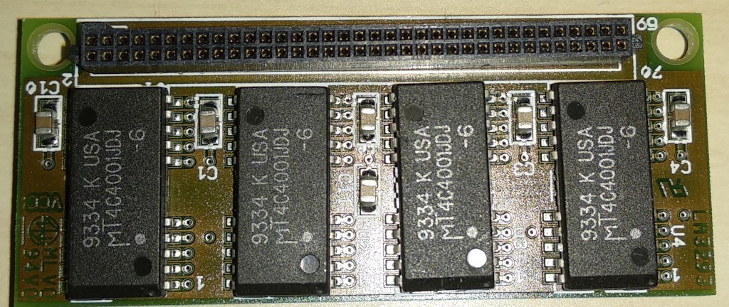
Memory
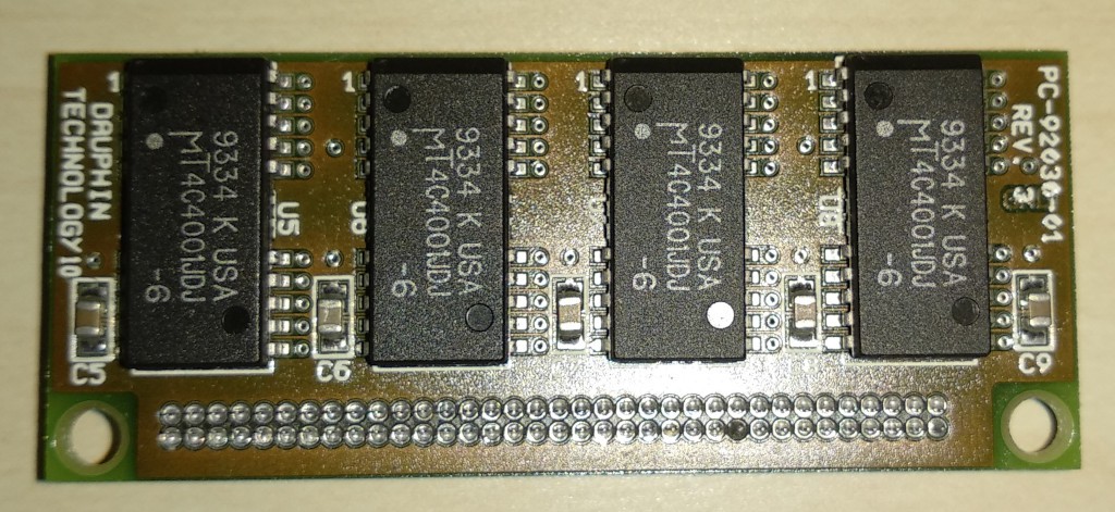
Memory subsystem in DTR-1 consists from two parts: 2Mb (4 chips 1Mx4) soldered on the motherboard and single connector for attaching the proprietary memory module. Manufacturer produced 2Mb and 4Mb modules, single and double sided: 4 chips of 1Mx4 on the one side of module for 2Mb and 8 chips of 1M4 on both sides for 4Mb.
In 2000 I've got the system with 2Mb single sided module and the lack of memory for Linux was the trigger to start upgrading the DTR-1. Simplifying, memory subsystem consists from pairs of 30pin 1Mb SIMMS, that gathered into 16 bit data bus. It's enough for 386SX and Cx484slc systems. DTR-1 actually do not use 8bit 30pin SIMMS, but topology and electrical connections between DRAM and memory controller are just the same as with SIMMs.
2Mb of integrated memory is the first pair of SIMMS, second pair is routed to the back side of the module, third pair - to the front side.
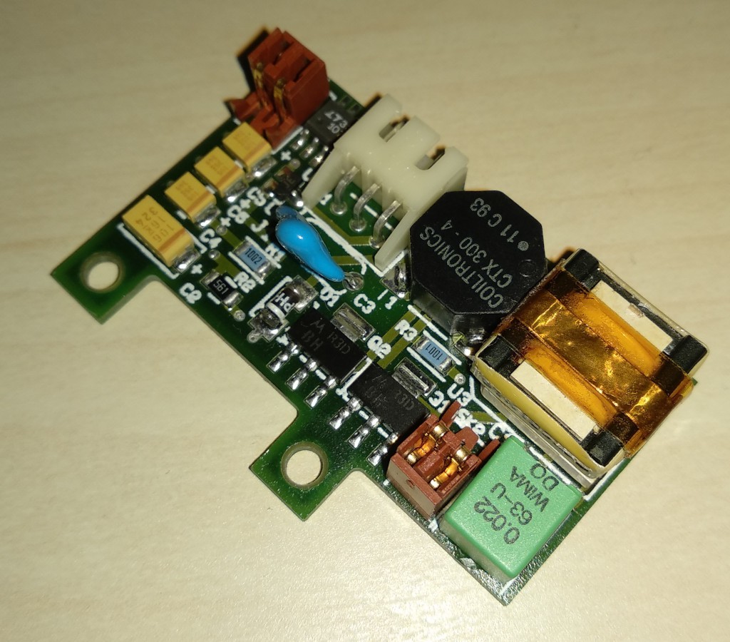
CCFL
High-voltage inverter for CCFL lamp are also implemented as the mezzanine card:
KBC+Touchscreen
KBC controller are implemented together with touchscreen controller. No 8042 MCUs are used in this board.Up to the current moment, it is the least rev.engineered board, except its connector.
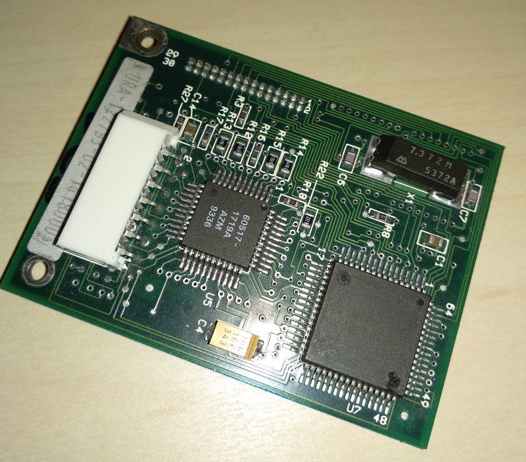
We'll investigate the motherboard more precisely in next articles.
Discussions
Become a Hackaday.io Member
Create an account to leave a comment. Already have an account? Log In.