Close
0%
0%

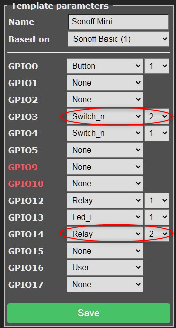
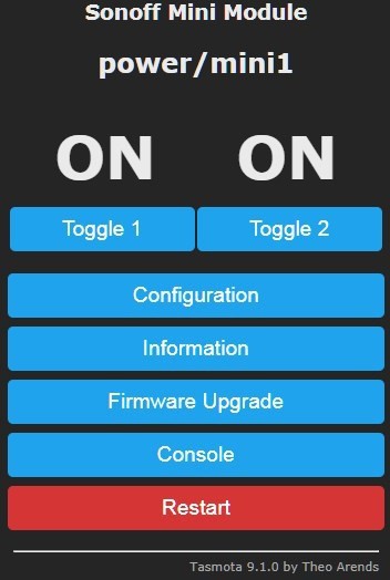
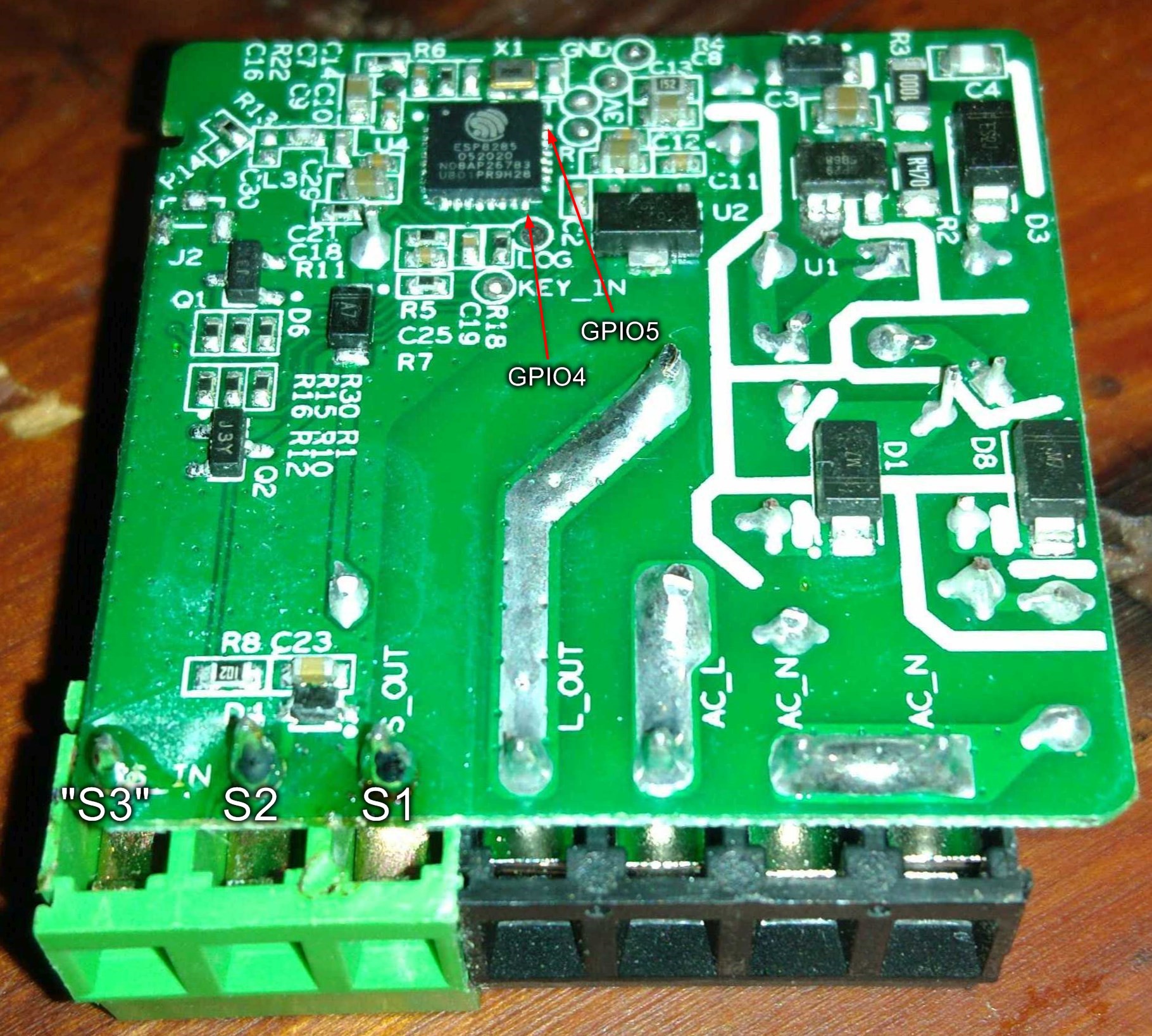
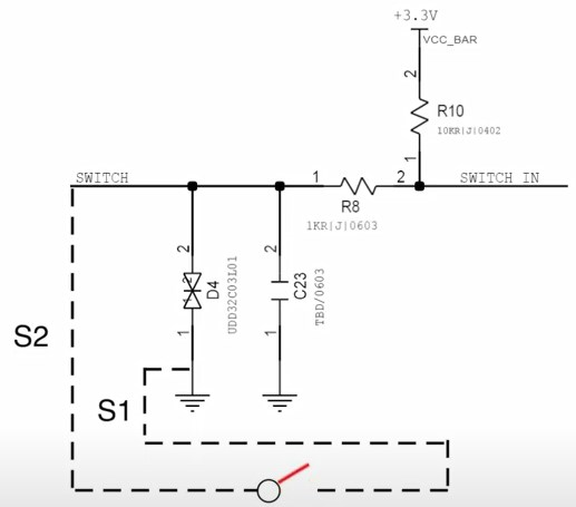
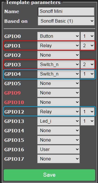
Sonoff Mini dual switch support

Add support to a second toggle switch to the Sonoff Mini

Similar projects worth following
Both of the locations I could use the Sonoff Mini in have dual wall switches, for inside and outside light. Really cannot use one side of a dual switch for low voltage and one for mains 230V, and don't want to lose the other side, so needed to make the Mini support those dual switches.

Note: These are mains voltage devices that really shouldn't be tampered with, if not exactly knowing what you are doing. As always, I won't be liable any way for any damage caused by any modifications mentioned here. These changes only affect the low voltage side of the device, but inside the device it is possible to cause dangerous, even lethal, changes.

Always cut mains power before touching the screw connectors and totally remove all wires to the device before opening it.

esp8285.jpg

ESP8285 GPIO pins

JPEG Image - 55.84 kB - 12/06/2020 at 21:38

Preview
Download

  • GPIO wired

    Turo Heikkinen12/08/2020 at 21:06 0 comments

    Wired GPIO3 (Rx) through a 1 kOhm resistor to the new screw terminal and pulled up with a 10 kOhm one, no capacitor or protection diodes so far but seems working fine, the device booting up in any switch position and all position combinations properly recognized.

    Before shrink wraps (too thick ones I admit) were shrank:

    The "S_OUT" terminal is tied to ground, will eventually add a bypass capacitor (like 0.1 - 1 uF) between that and the new terminal.

    In Tasmota template configuration I defined GPIO3 to be Switch 2 and to see the state of the other switch, defined the unused GPIO14 to be an imaginary "Relay 3". Tasmota doesn't directly show switch states (yet) but does show states of relays, real or not, and relayX by default follows switchX, essentially showing my switch state.

    Note that I have set switches to "Switch_n", which just means the internal pull-up resistors aren't used, as I have the external resistors. Without the "_n" you could do without the 10 kOhm pull-up resistor, but whenever not too inconvenient, I like to set my pull-ups explicitly in hardware.


    In the main page I can see the switch states, unless I have changed them by MQTT or these buttons. The first ON & Toggle combo are linked to the real on-board relay, the other group just to one unconnected GPIO, but that's fine as I just want to get the switch state to Node-Red, and just in case be able to control and see it here.

    Using the serial Read pin as input doesn't seem to affect normal usage of the device, but could as well disable serial logging (dunno if it affects Rx really but might disable hardware serial). The command is "SerialLog 0":

    Tasmota documents using buttons and switches here. The interesting options are SwitchTopic and SwitchMode.

    After reading the documentation I wasn't completely sure (an English phrase meaning "no slightest clue") how they actually worked, so here's some simple testing:

    SwitchTopic2 0

    22:12:42 MQT: stat/power/mini1/RESULT = {"POWER2":"OFF"}
    22:12:42 MQT: stat/power/mini1/POWER2 = OFF

    SwitchTopic2 1

    22:09:51 MQT: cmnd/power/mini1/POWER2 = OFF  <<---The MQTT command summoned by the "SwitchTopic 1" spell
    22:09:51 MQT: stat/power/mini1/RESULT = {"POWER2":"OFF"}
    22:09:51 MQT: stat/power/mini1/POWER2 = OFF

    So, doesn't really matter, I get some MQTT anyway. Without the "virtual relay" might matter.

    "SwitchMode 0" and "SwitchMode 1" (or 2 for inverted) work exactly the same when just the physical switched used, but with "0" it gets out of sync if MQTT or the buttons are used to switch the state. With "0" any change of the switch changes the state, even if it already was in the logical target state, with "1" the mechanical switch stays in sync with the button. "2" would be an "inverted 1", if the logical on/off states are opposite to what Tasmota shows. "2" is the one that I'm using as then a closed switch would be shown as "On" in Tasmota.

    Which SwitchMode is for you?

    • If you could draw "On" to one side of the switch and "Off" to the other (like conventional room light switch), use "1"
    • A variation of the previous line, if Tasmota shows the switch state opposite to what you'd expect, use "2"
    • If the physical position of the switch(es) doesn't relate to the expected state (like a corridor/stairway pair), use "0"

    To check the actual state of the switches, you can use the "status 10" command:

  • Figuring out the best way to do it

    Turo Heikkinen12/06/2020 at 22:03 0 comments

    So, there is one input and I need two - easy task as there are only four GPIOs used (button, relay+led, another LED, S2) and all the open firmwares support using any GPIO for anything. The stock Sonoff firmware I didn't look at, I prefer to control my devices myself instead of some Chinese cloud service.

    I see a ESP8285 on the PCB so I already know it can be done. First drilled one more hole for replacing the stock gray (black in V1) two wire screw terminal by a three wire one, using a piece of proto board as a template .

    Then need to figure out the most convenient GPIO to connect the new input to, GPIO0 and 2 would have nice pads, but the device won't boot, if any of those in a wrong state thus need to use something else.

    Didn't find a convenient pin layout diagram for the 8285 so added GPIOs to the datasheet's diagram:

    Stock GPIOs:

    • 0: Input, button (doubling as flash mode switch), wired to a pad
    • 1: Wired to the Tx pad
    • 2: Available, wired to a pad, but having boot restrictions
    • 3: Wired to the Rx pad, might be viable
    • 4: Input, S2 switch screw terminal
    • 5: Available, no pad
    • 6, 7, 8, 9, 10: Used by internal flash (long story short)
    • 12: Output, relay and red LED
    • 13: Output, blue LED
    • 14: Available, no pad
    • 15: Boot restrictions
    • 16: OTA jumper in V1, apparently not used in V2. Cannot be tied to ground, doesn't support interrupts etc.

    GPIOs 5 and 14 are available, fully free to use and both are the last pin of their row so relatively accessible, but need soldering to the tiny 0.5 mm pads, which might need some practice and microscope (both of which I do have but prefer to productise stuff to be applicable to broader public).

    GPIO 3 = Rx has a pad and doesn't look to be used for anything (except flashing of course), might be a more convenient choice.

    In the older V1 version (with external antenna included, V2 has a tiny internal antenna and pads for an external one) GPIO 16 is routed to a 2 pin header, thus might be viable in V1 (just use a resistor between the pin and ground) but not in V2.

    At least in the V2, the S2 input is connected to the pin (GPIO 4) via a 1kOhm resistor, and the pin is pulled up by a 10 kOhm resistor:

    In addition to the resistors there is a ceramic capacitor C23 (measured 32 uF in my devices) and a transient-voltage-suppression diode array D4 protecting against possible high voltage pulses induced to the switch line.

    I'd suggest adding at least similar-ish resistors and some capacitor (value is not critical, something like 1 uF should do fine) to the new line. The protection diode array would be good to have but if you're not going to accidentally connect mains voltage to the switch line and your location doesn't have much lightning spikes, it'll probably be fine without (your consideration of course, I'm not recommending this).

View all 2 project logs

  • 1
    Flash the Sonoff Mini with Tasmota

    The Sonoff mini has a "DIY mode", which is for you, if you prefer learning a new rather complex proprietary process instead of wasting two seconds to pop open the case and another 45 to align a prommer to the flashing pads and flashing the normal way. I was too lazy (as engineers are - if we weren't lazy, we would still spend our days running after the next species to finish) and just popped out the case to find the row of flashing pins, wired my pogo comb properly to the UART  (see the picture) and flashed the latest Tasmota with Tasmotizer or Tasmota-Pyflasher.

    To get to the flashing mode, keep the button on the other side pressed while powering/resetting the device. Or adjust one pogo pin at the "KEY_IN" pad and use a flashing adapter's flashing control button.

    Of course you can as well just solder the 4-5 wires (use thin coated wire like wire wrap wire) to the pads, not much slower if you got only one device to flash.

    After flashing, power the device either by any 3V3 or 5V pads inside, or by assembling the device and connecting AC wires to the N & L In terminals. When powered, follow Tasmota instructions; first connect phone or something to the device's AP, write down the MAC address (I always scribe that on the device case with a permanent felt pen), open 192.168.4.1 with a browser, configure WiFi, reboot, find device with Fing/router DHCP list/whatever (now having the MAC address helps), point your browser to that address, configure the rest.

    Now we can use the vanilla Sonoff Mini template: {"NAME":"Sonoff Mini","GPIO":[17,0,0,0,9,0,0,0,21,56,0,0,255],"FLAG":0,"BASE":1}

    The device's Tasmota main page should now show one "ON" or "OFF" and "Toggle", check that the Toggle button changes the relay state, you should hear a relay click.

  • 2
    Add the new terminal

    Detach AC wires, pry open the device with a screwdriver/club card/<insert your favourite tool>, find the screw terminal blocks. In V2 the switch terminals are gray, in V1 black, find the ones marked S_IN and S_OUT = the ones with no thick solder snakes coming from them.

    Those screw terminal blocks as 2-way and 3-way are very common; you probably have a practically vacant 3-way one in some Chinese device which you never figured out how to use as your Mandarin sucks. Or already have bagful of those waiting for this exact moment (now you know), like I did. With a hot soldering iron solder and pry off the S_IN / S_OUT block (minor violence required, the block has a small tab inside its neighbour). Use a piece of proto board as a template and drill a 1.5 mm (take the inch conversion as homework, if needed) hole two proto board holes away from S_IN. Place a 3-way screw terminal in the holes, solder.

    Now that we have the terminal, need to wire a GPIO to that. GPIO3 = RxD has a nice pad and we won't probably need it for serial communication anymore so lets use that. The stock switch circuit has a 1 kOhm resistor between the terminal and GPIO, lets do the same. To get a good pull-up for the pin when the switch is open, wire a 10 kOhm (copied from the stock S_IN circuit) between the terminal and the 3V pad.

    Should look somewhat like this before moving the shrink tube pieces around the exposed resistor ends to be shrunk:

    The stock circuit also has a noise filter capacitor (I measured 32 uF but can be much smaller, down to maybe 0.1 uF, bigger makes it slower which may help in (electrically) noisy conditions) between the terminal and ground. Could now, or when having strange spontaneous state changes, add a 0.1uF or bigger capacitor between the terminal and S_OUT (=ground). The original circuit also has a transient-voltage-suppression diode array D4 for protection against lightnings etc spikes, that wouldn't be a bad idea.

    After wired and careful visual checking (you want to get the loose solder blobs away before connecting to AC), assemble the device again, attach AC, check if the IP address still responds.

  • 3
    Configuring Tasmota

    Now that we have the dirty stuff done, lets make Tasmota know about it. Open browser at the device's IP address, you should see the Tasmota main page. First click "Console" and there type "SerialLog 0"<enter>, that will free the serial lines to us:

    Navigate to Main Menu->Configuration->Template, add a switch and a relay (more about that later):

    Blue ones are the stock relay and S1 / S2 switch, red ones are the new ones.

    I have defined the switches as Switch_n as that disables ESP's built-in pull-ups, which are not needed as we have external resistors. Just a tiny amount of electricity consumption = heat removed from the chip this way, no functional difference. Professionally I have learned to be careful with these tiny currents that tend otherwise cumulate to be huge.

    Defining GPIO3 as "Switch" and leaving out the 10 kOhm pull-up resistor would probably work fine as well; the internal pull-ups just are rather weak and I prefer to pick values myself.

    After clicking Save the device will reboot and you'll see something new on the main page:

    The shiny new rightmost set of ON / Toggle are the "relay" at GPIO1 we just defined - there is no real relay but Tasmota doesn't know that and shows us nice state display and control for that. The stock switch input is now Switch1 on the left and the new one is Switch2 on the right, and these switches are automatically linked to the relays "1" = the real one and "2" = a virtual one that is just a GPIO.

    Now that we are done with the UI, lets go to Console. Some commands we could use:

    • SwitchMode<switch number> <mode> - Configure the switch type; mode = 0 for corridor/stairway switch pairs where switch orientation doesn't relate to the state, mode = 2 for conventional switches with "On" and "Off" positions. Mode = 1 would be this inverted, if need to swap "On" and "Off". For example: SwitchMode2 2 - set the new switch to normal on/off mode.
    • PowerOnState<relay number> <mode> - Configure the initial mode of "relays" after startup, 0=off, 1=on, 3=keep last. Unfortunately so far no mode to use whatever the switches are set to.
    • SerialLog 0 / 1 - This disables or enables (when no external wires connected) serial logging so that we can use the pins for our purposes, or get logging if needed

    That's pretty much it, you should now have a Sonoff Mini connectable to a dual switch where one switch affects the relay (and sends MQTT messages) and the other just sends MQTT to control a light somewhere or do anything you like. Just as these things should.

View all 4 instructions

Enjoy this project?

Share

Discussions

Similar Projects

Does this project spark your interest?

Become a member to follow this project and never miss any updates