 Turo Heikkinen
So, there is one input and I need two - easy task as there are only four GPIOs used (button, relay+led, another LED, S2) and all the open firmwares support using any GPIO for anything. The stock Sonoff firmware I didn't look at, I prefer to control my devices myself instead of some Chinese cloud service.
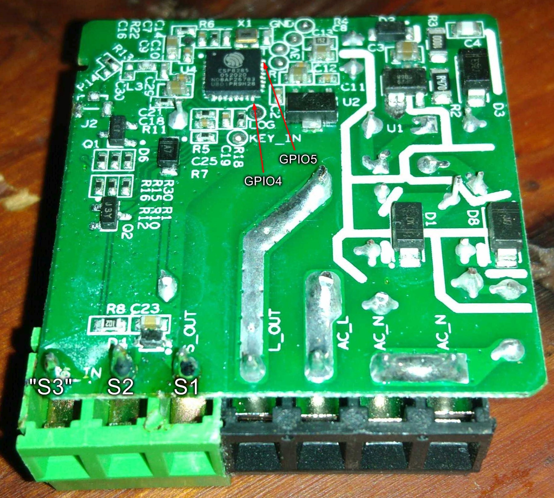
I see a ESP8285 on the PCB so I already know it can be done. First drilled one more hole for replacing the stock gray (black in V1) two wire screw terminal by a three wire one, using a piece of proto board as a template .
Then need to figure out the most convenient GPIO to connect the new input to, GPIO0 and 2 would have nice pads, but the device won't boot, if any of those in a wrong state thus need to use something else.
Didn't find a convenient pin layout diagram for the 8285 so added GPIOs to the datasheet's diagram:
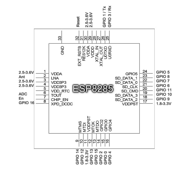
Stock GPIOs:
- 0: Input, button (doubling as flash mode switch), wired to a pad
- 1: Wired to the Tx pad
- 2: Available, wired to a pad, but having boot restrictions
- 3: Wired to the Rx pad, might be viable
- 4: Input, S2 switch screw terminal
- 5: Available, no pad
- 6, 7, 8, 9, 10: Used by internal flash (long story short)
- 12: Output, relay and red LED
- 13: Output, blue LED
- 14: Available, no pad
- 15: Boot restrictions
- 16: OTA jumper in V1, apparently not used in V2. Cannot be tied to ground, doesn't support interrupts etc.
GPIOs 5 and 14 are available, fully free to use and both are the last pin of their row so relatively accessible, but need soldering to the tiny 0.5 mm pads, which might need some practice and microscope (both of which I do have but prefer to productise stuff to be applicable to broader public).
GPIO 3 = Rx has a pad and doesn't look to be used for anything (except flashing of course), might be a more convenient choice.
In the older V1 version (with external antenna included, V2 has a tiny internal antenna and pads for an external one) GPIO 16 is routed to a 2 pin header, thus might be viable in V1 (just use a resistor between the pin and ground) but not in V2.
At least in the V2, the S2 input is connected to the pin (GPIO 4) via a 1kOhm resistor, and the pin is pulled up by a 10 kOhm resistor:
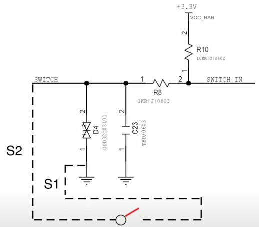
In addition to the resistors there is a ceramic capacitor C23 (measured 32 uF in my devices) and a transient-voltage-suppression diode array D4 protecting against possible high voltage pulses induced to the switch line.
I'd suggest adding at least similar-ish resistors and some capacitor (value is not critical, something like 1 uF should do fine) to the new line. The protection diode array would be good to have but if you're not going to accidentally connect mains voltage to the switch line and your location doesn't have much lightning spikes, it'll probably be fine without (your consideration of course, I'm not recommending this).
Discussions
Become a Hackaday.io Member
Create an account to leave a comment. Already have an account? Log In.