 Turo Heikkinen
Wired GPIO3 (Rx) through a 1 kOhm resistor to the new screw terminal and pulled up with a 10 kOhm one, no capacitor or protection diodes so far but seems working fine, the device booting up in any switch position and all position combinations properly recognized.
Before shrink wraps (too thick ones I admit) were shrank:
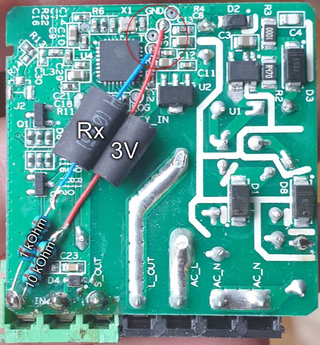
The "S_OUT" terminal is tied to ground, will eventually add a bypass capacitor (like 0.1 - 1 uF) between that and the new terminal.
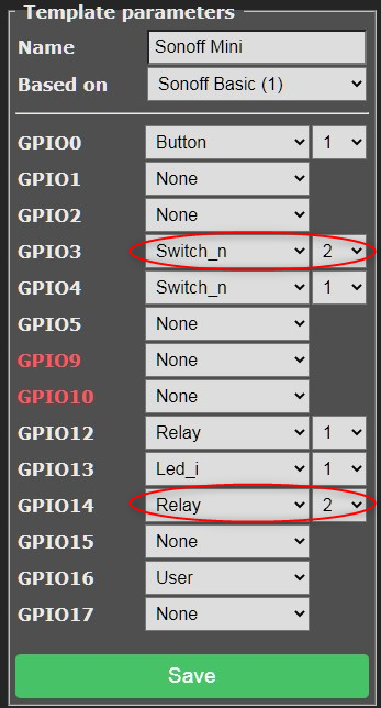
In Tasmota template configuration I defined GPIO3 to be Switch 2 and to see the state of the other switch, defined the unused GPIO14 to be an imaginary "Relay 3". Tasmota doesn't directly show switch states (yet) but does show states of relays, real or not, and relayX by default follows switchX, essentially showing my switch state.
Note that I have set switches to "Switch_n", which just means the internal pull-up resistors aren't used, as I have the external resistors. Without the "_n" you could do without the 10 kOhm pull-up resistor, but whenever not too inconvenient, I like to set my pull-ups explicitly in hardware.
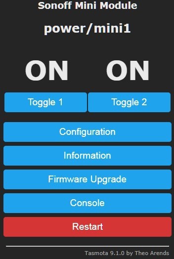
In the main page I can see the switch states, unless I have changed them by MQTT or these buttons. The first ON & Toggle combo are linked to the real on-board relay, the other group just to one unconnected GPIO, but that's fine as I just want to get the switch state to Node-Red, and just in case be able to control and see it here.
Using the serial Read pin as input doesn't seem to affect normal usage of the device, but could as well disable serial logging (dunno if it affects Rx really but might disable hardware serial). The command is "SerialLog 0":
Tasmota documents using buttons and switches here. The interesting options are SwitchTopic and SwitchMode.
After reading the documentation I wasn't completely sure (an English phrase meaning "no slightest clue") how they actually worked, so here's some simple testing:
SwitchTopic2 0
22:12:42 MQT: stat/power/mini1/RESULT = {"POWER2":"OFF"}
22:12:42 MQT: stat/power/mini1/POWER2 = OFF
SwitchTopic2 1
22:09:51 MQT: cmnd/power/mini1/POWER2 = OFF <<---The MQTT command summoned by the "SwitchTopic 1" spell
22:09:51 MQT: stat/power/mini1/RESULT = {"POWER2":"OFF"}
22:09:51 MQT: stat/power/mini1/POWER2 = OFF
So, doesn't really matter, I get some MQTT anyway. Without the "virtual relay" might matter.
"SwitchMode 0" and "SwitchMode 1" (or 2 for inverted) work exactly the same when just the physical switched used, but with "0" it gets out of sync if MQTT or the buttons are used to switch the state. With "0" any change of the switch changes the state, even if it already was in the logical target state, with "1" the mechanical switch stays in sync with the button. "2" would be an "inverted 1", if the logical on/off states are opposite to what Tasmota shows. "2" is the one that I'm using as then a closed switch would be shown as "On" in Tasmota.
Which SwitchMode is for you?
- If you could draw "On" to one side of the switch and "Off" to the other (like conventional room light switch), use "1"
- A variation of the previous line, if Tasmota shows the switch state opposite to what you'd expect, use "2"
- If the physical position of the switch(es) doesn't relate to the expected state (like a corridor/stairway pair), use "0"
To check the actual state of the switches, you can use the "status 10" command:
Discussions
Become a Hackaday.io Member
Create an account to leave a comment. Already have an account? Log In.