 Juan-Antonio Søren E.P.
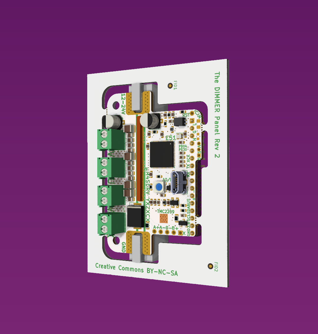
The controller is now ready for testing. Have had to do a few changes to insure good system reliability.
* Since the controller can be used as a BLDC or stepper controller, I have upgraded the TVS diode package.
* The 5V LDO have been upgraded to MSOP8 packgate (500mA continuus) from SOT 23-5 (only 200mA continuus).
* Screw terminals has been upgraded to 3.5 pitch, which has a 17.5amp rating, thats 35 amp per phase (Continuus). Each terminal is rated to carry two conductors. This means 4 separate LED modules w. 4 channels can be powered/dimmed from a single controller. Do note that each half bridge is 60 amp rated. I would under no circumstance recommend to go beyond 1000WATT because of switching loss´s (depending on switching freq. and passive or active cooling).
* Main power wire lugs has been upgraded to 85 amp rated from 65 amp rated. Do note that the lugs will get hot at 85 amp. The 65 amp lug can still be used. Wires can also be soldered directly on to the board, eg. if the controller should be integrated into a CNC routed heatsink/housing.
* Microchip (ATSAME51 MCU producer) advises to use a ferrite bead in series with the analog power domain supply, for some applications. This is to filter out digital noise before it hits the ADC/DAC. So I have chosen to follow their advice. The bead should be carefully chosen for DC filtering w. lowest possible resistance.
* Moved the 3 analog hall sensors, so that all 3 is aligned to center of rotation for NEMA23. For bigger steppers a 3D printed bracket can be used.
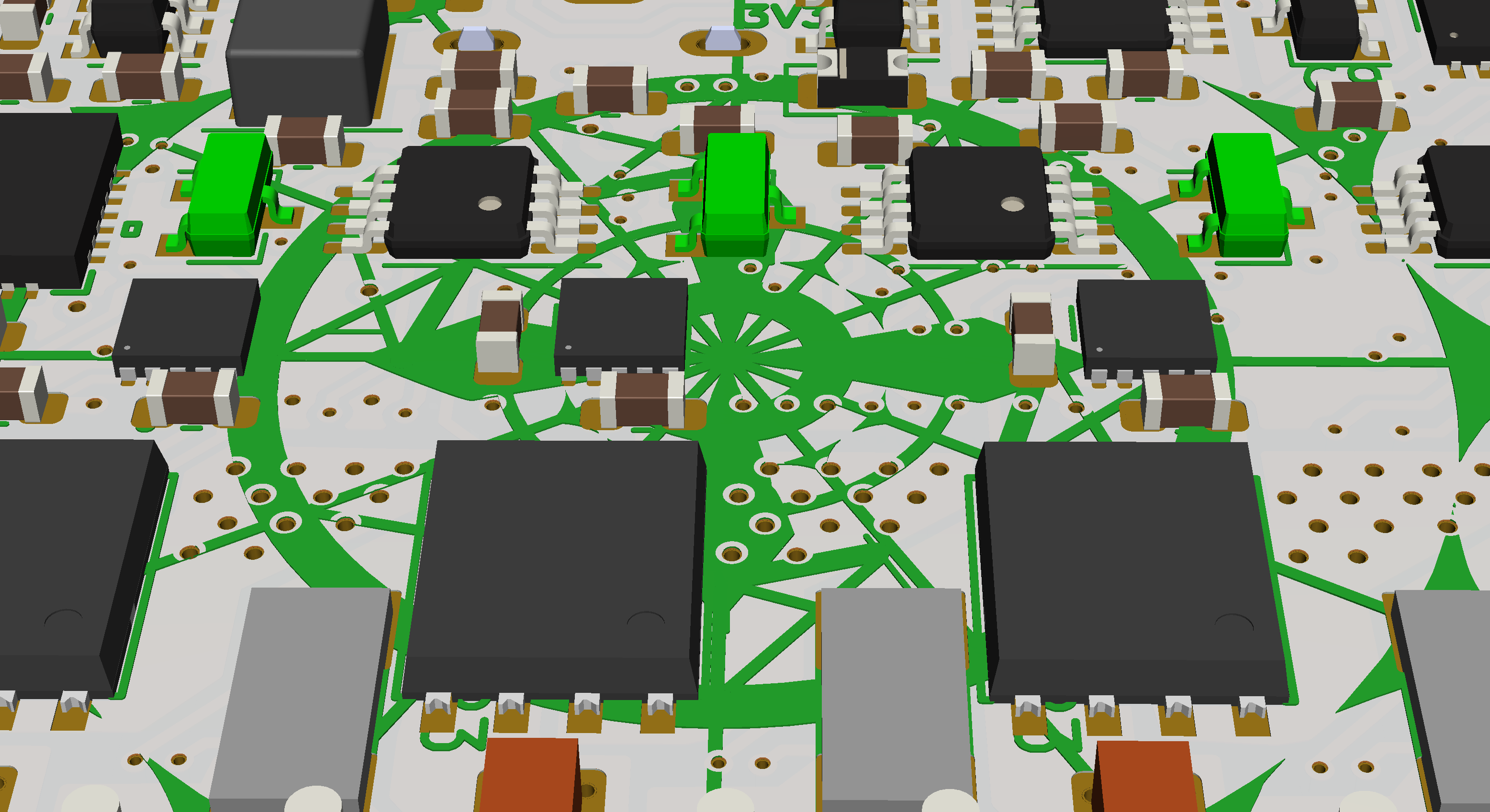
The 3 hall sensors highlighted in green placed to cover 30 degrees. The ADC (Analog to digital converter) of the SAME51 can make 1.000.000 samples per second. The MCU has two seperate ADC´s of which ADC0 is used for on board measurements (Not including A0/DAC which is broken out) Two pins on ADC1 is broken out for external use. Pin functionality will be mapped in code. Broken out pins can also be regular IO/EXTINT.
Discussions
Become a Hackaday.io Member
Create an account to leave a comment. Already have an account? Log In.