 Max.K
Max.KFor connecting the keyboard to a computer, USB was the obvious choice. Not having to care about low-energy was a welcome change from my previous, mostly battery-powered projects. The first microcontroller that came to my mind was the Atmega32U4 as it has built-in USB support and does not need a separate USB to serial converter. But one problem is its small SRAM with only 2kB. When using displays their pixel values are usually saved in RAM, so that the image can be easily manipulated. For a first iteration of the keyboard, I was planning to use nine OLEDs with 64x48 pixels each. This adds up to 3456 bytes of memory. It would be possible to use the Atmega with some software trickery, like keeping only one screen in memory and cycling through them. But I did not want to risk running into performance problems later. Instead, I decided to use the ST STM32F1 as it is cheap, has USB support and upwards of 20kB RAM. It also is officially Arduino-compatible, known for being used in the Blue-Pill boards.
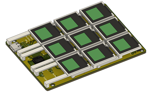
With all parts select I created a compact PCB that would hold nine OLEDs. The board contains mounting point for the 3D-printed button mechanism. On the “chin” of the device, where the levers of the last row of screen sit, there is just enough room for a USB-C connector and the STM32F1.Ultimately the wiring of this PCB is very simple. The STM32 is supplied by the USB connection and a 3.3V regulator. The regulator (AP2112K) also powers the nine LEDs, which contain internal dc-dc converters to create their working voltage of around 9V. USB-C is used for the connector, but it is wired as regular USB2.0. As the OLEDs can only assume one of two I²C addresses I had to use SPI. That means they share all data lines but they each have their own chip select.

Assembling the board can be tricky as the OLEDs have to be soldered in first before the 3D-printed mounts are put in place. There is only enough room to get them in place in a certain order without damaging the display connectors. I did not want to leave the PCB and mechanisms exposed so designed and printed a simple case. The PCB snaps into it and the buttons get covered with a face plate. I originally planned to put transparent acrylic on the OLED panels, but it looks much nicer without them. As the screens are made from glass, scratches should not be a big issue.

The STM32 can be programmed via USB after initially flashing the USB bootloader (stm32duino bootloader). Currently there are two different Arduino implementations for the STM32 boards. An official one by ST and the Arduino_STM32 port by Roger Melbourne. The latter contains more features, including some that are needed for this project. To make the keyboard work as a HID (human interface device) I used the STM32F1 USB composite library. With this library the STM32 cannot just mimic a HID device, but a serial port simultaneously. This enables the keyboard to be controlled over a COM port while still being an independent HID keyboard. The firmware I created is very simple as the Adafruit GFX library includes most the code needed to drive the displays. What turned out to be much more complicated was the desktop app that would be used to control the keyboard.
Discussions
Become a Hackaday.io Member
Create an account to leave a comment. Already have an account? Log In.