The project was to enlarge the hole in a piece of hardened steel. The existing hole is what made the project so simple. The idea is to move electrolyte through the hole while passing a DC current through it. The metal surrounding the hole will be dissolved into the electrolyte thereby enlarging the hole. A jig was made that would keep the electrolyte from reaching any part of the workpiece that wasn't intended to be removed. The setup is shown below:
Figure 1
The workpiece is a wrench which is clamped to a piece of wood.
The jig is attached to the far end of the wrench.
There is a pail to catch the electrolyte after it has passed through the jig.
Note the plastic tube which leads to a 20 litre bottle of salt water. The tube is a siphon.
The spring clamp is used to pinch off the syphon.
The positive terminal of a 24 volt power supply is clipped to the workpiece (ie. the wrench).
The negative terminal of the power supply is clipped to the copper tube that feeds the electrolyte to the jig.
Figure 2
This is a section drawing of the jig.
Note that the end of the copper tube stops short of actually touching the workpiece. Otherwise, a short circuit would result.
Figure 3
This is an exploded drawing of the jig.
The gaskets are rubber tape with ragged 8 mm holes drilled in them.
The tape at the bottom of the jig has a 3 mm hole drilled in it. It's purpose is to reduce the flow of electrolyte and to ensure that the electrolyte establishes proper electrical contact with the workpiece.
Results
The current was about 0.6 amps throughout the job which lasted about an hour. The power supply output was 24 volts. The hole in the wrench was enlarged from 7.5 mm to 9.5 mm. The hole is not particularly circular. Its diameter ranges from about 9 mm to about 10 mm.
Discussion
The biggest surprise was that the hole's edges were quite sharp. My reading led me to believe that sharp edges are hard to achieve with ECM. One possibility is that the paint on the surface of the workpiece would overhang the edge for a while before collapsing thus reducing the electrolyte's access to the edge.
Normally, the gap between the tool and the workpiece is quite small. In this case the distance between the end of the copper tube and the workpiece was at least a couple of mm. That reduced the DC current thus increasing the machining time. It probably also decreased the accuracy of the machining.
The thick rubber gaskets appear to have deformed when the jig was assembled. That would also have affected the accuracy of the machining.
Since the hole is contained within the jig, it was necessary to calculate the machining time to determine when to stop.
I calculated a machining time of about an hour. When the job was done and the jig was disassembled, it was found that the hole was about the right size. The problem is that I found an error in my calculation. The job should have taken twice as long.
Is it possible that the formula is wrong for this case? The calculation was close to the actual result. I thought I found an error but that was wrong. That said, I spent some time trying to figure out why the formula might not work.
The spent electrolyte was recycled back into the 20 litre bottle without filtering. Shining a laser beam down a column of that electrolyte produces scattering. That indicates particles larger than a nanometer in diameter.

If the iron is coming off the workpiece in particles larger than a nanometer, that might invalidate the formula.
Another thing is that, because of the wide gap and high voltage, there are plenty of oxygen and hydrogen ions present. That might give rise to a chemical reaction that also strips iron from the workpiece. That might also invalidate the formula.
Given that there are things that might go wrong, the MRR (Material Removal Rate) formula seems pretty robust.
Reference: http://www.home-machine-shop.com/Down-Load/Electrochemical_Machining.pdf...


 agp.cooper
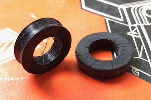
 Michael O'Brien
 Ted Yapo
The current was pretty constant around 0.6 amps for most of the hour. Near the beginning it bumped up to about an amp for a minute or so. You would think the current would have decreased as the workpiece eroded away from the tool but that doesn't seem to have happened. I was a bit surprised at how low the current was. The conductivity of the electrolyte was about 5 ohms per cc.