Overview
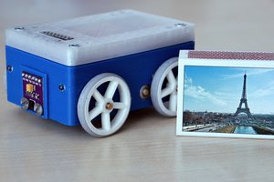
This is a passion project. I have always wanted to build a balancing robot. I made an attempt years ago but it never really got the attention that it needed. Plus, life has a way of steering your attention away. Now with new found motivation, 1 or 2 hours a day, and a 3D printer, I have decided to give it another go.
Currently the main goal of the robot is for it to balance on it's own and to be controllable via a bluetooth controller. The robot itself uses similar components found on the many balancing robots scattered across the internet. An arduino platform for the brains, an IMU module to sense the robots tilt, motor drivers and motor. A list of all components used on this robot can be found in the Components section, but I will use this Project Details section to show and explain some of the components and design decisions.
Brains
The brains of the robot is a Sparkfun SAMD21 Mini Breakout board.
This module is compatible with the Arduino IDE, has a relatively small footprint and has a higher performance microcontroller compared to some of the other Arduino platforms available.
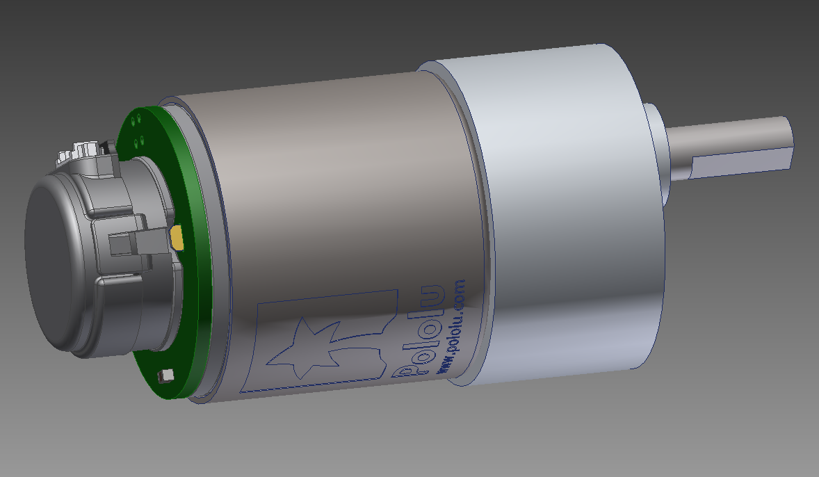
Motor and Motor Driver
The motors that were selected is the 6.3:1 Metal Gearmotor 37Dx65L mm 12V with 64 CPR Encoder (Helical Pinion) from Pololu.
The specs for this motor can be found on their website so I will not repeat it here. Originally, stepper motors were chosen but I did not like the amount current needed by stepper motors and the heat that they can generate. Since the structure of the robot will be made with 3D printed parts, DC motor were selected instead. Plus the DC motors have encoders which is used by the robot.
To drive the motors, I have selected the G2 High-Power Motor Driver 18v17 from Pololu.
Again, specs are available on their website. Now these drivers are more than capable to drive the DC motors that I have selected. I could have chosen other drivers that are cheaper and lower power, but these were selected in case I wanted to recycle them for other projects that may need more power.
IMU
The Inertial Measurement Unit selected is the AltIMU-10 v5 from Pololu.
This module has gyro, accelerometer, compass and altimeter on board. For this robot, only the gyro and accelerometer are used. Again, definitely more than is needed for this robot. It is also helpful that there is an arduino library for the LSM6DS33 3-axis gyroscope and 3-axis accelerometer IC that is on this module.
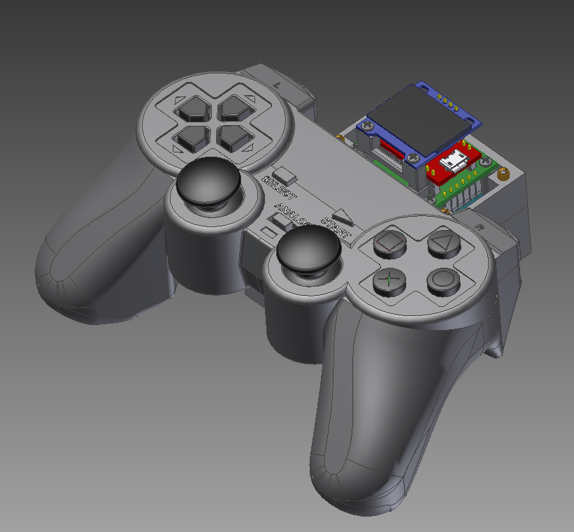
Bluetooth
For wireless communication, a generic HC-06 Bluetooth module was selected.
This module allows wireless serial communication via Bluetooth. The robot uses this to send telemetry data and receive commands to and from a PC or controller.
Voltage Regulator
The robot is powered by a 9.6v NiMH battery. Most of the components need a 5V supply, so a voltage regulator is needed. The voltage regulator selected is the 5V Step-Up/Step-Down Voltage Regulator S9V11F5 from Pololu.
This was selected for it's high efficiency and relatively high current output. An additional 33uF capacitor was added to the input of the regulator module to handle any initial voltage spikes. This is based on Pololu's recommendation for this module.
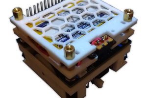
Custom Carrier Board
A custom carrier board was designed in KiCad to hold all these modules.
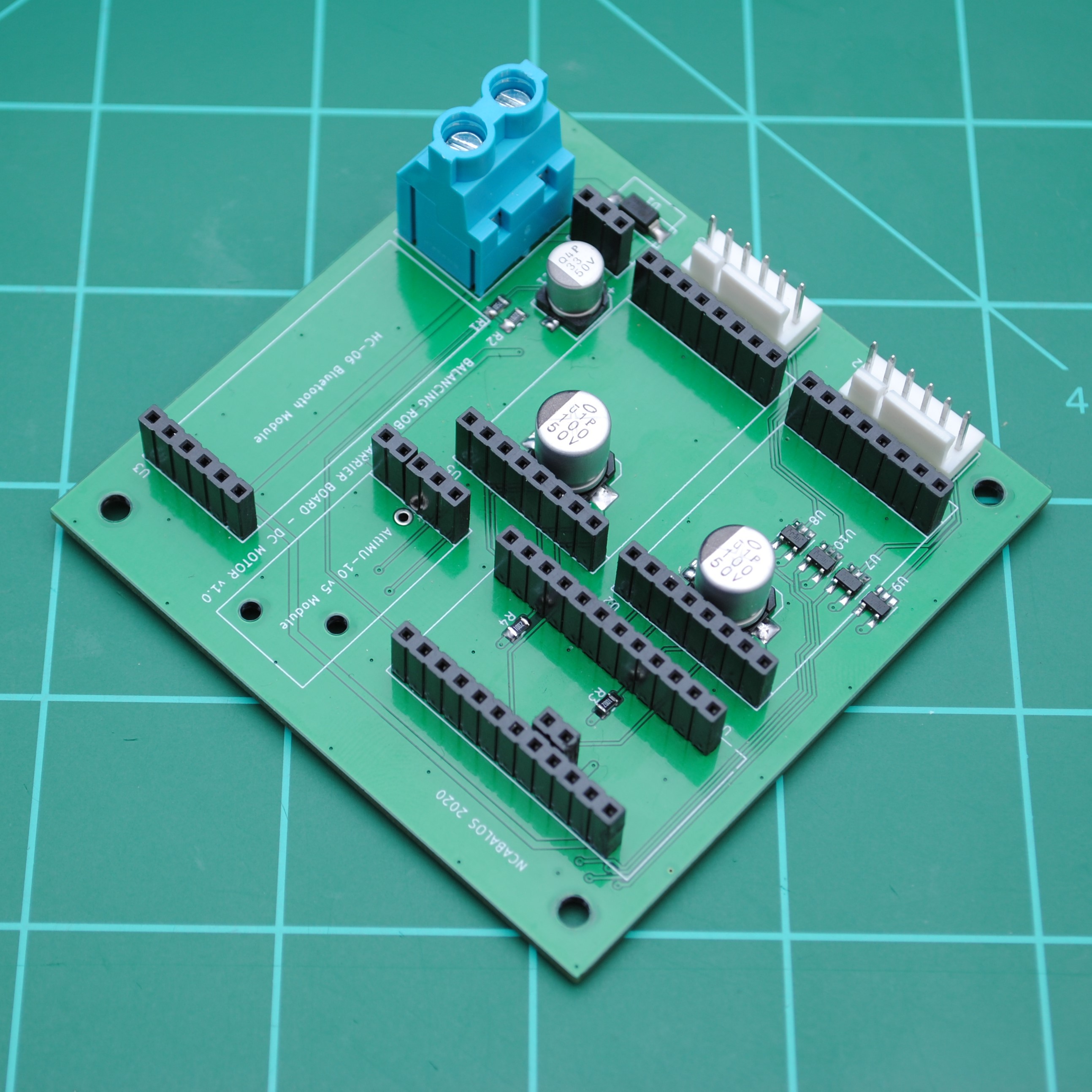
The carrier board contains some support circuits needed by the different modules:
- Capacitors for the motor drivers
- Logic level translators for the encoder inputs. The encoder signals from the DC motor is 5V and the IO on the Sparkfun SAMD21 Mini Breakout Board is not 5V tolerant.
- Reverse voltage protection.
- Voltage divider for the battery voltage measurement circuit.
- Filter capacitor for voltage regulator module
- Pull-up resistors for some motor driver signals.
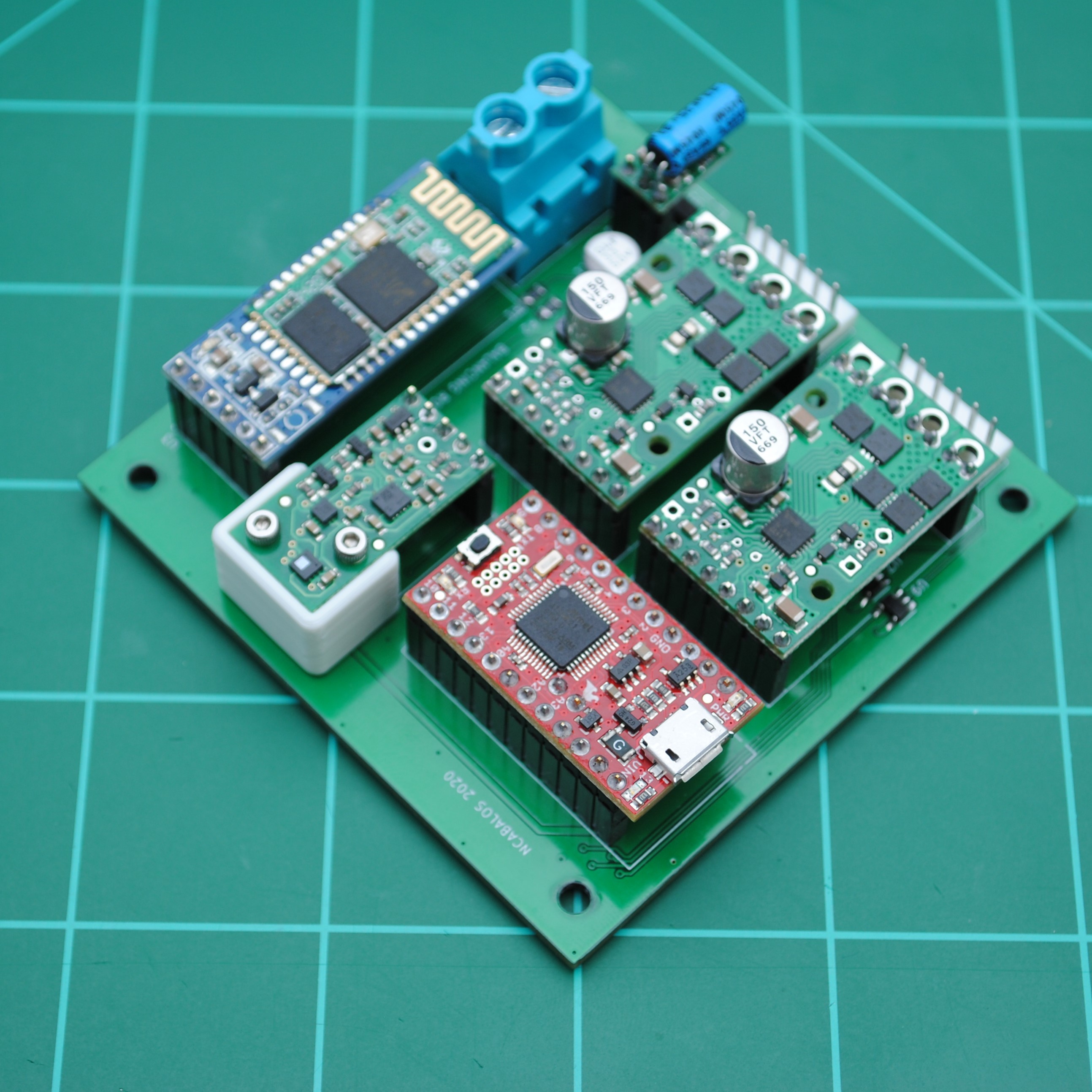
Here is the carrier board with modules populated:
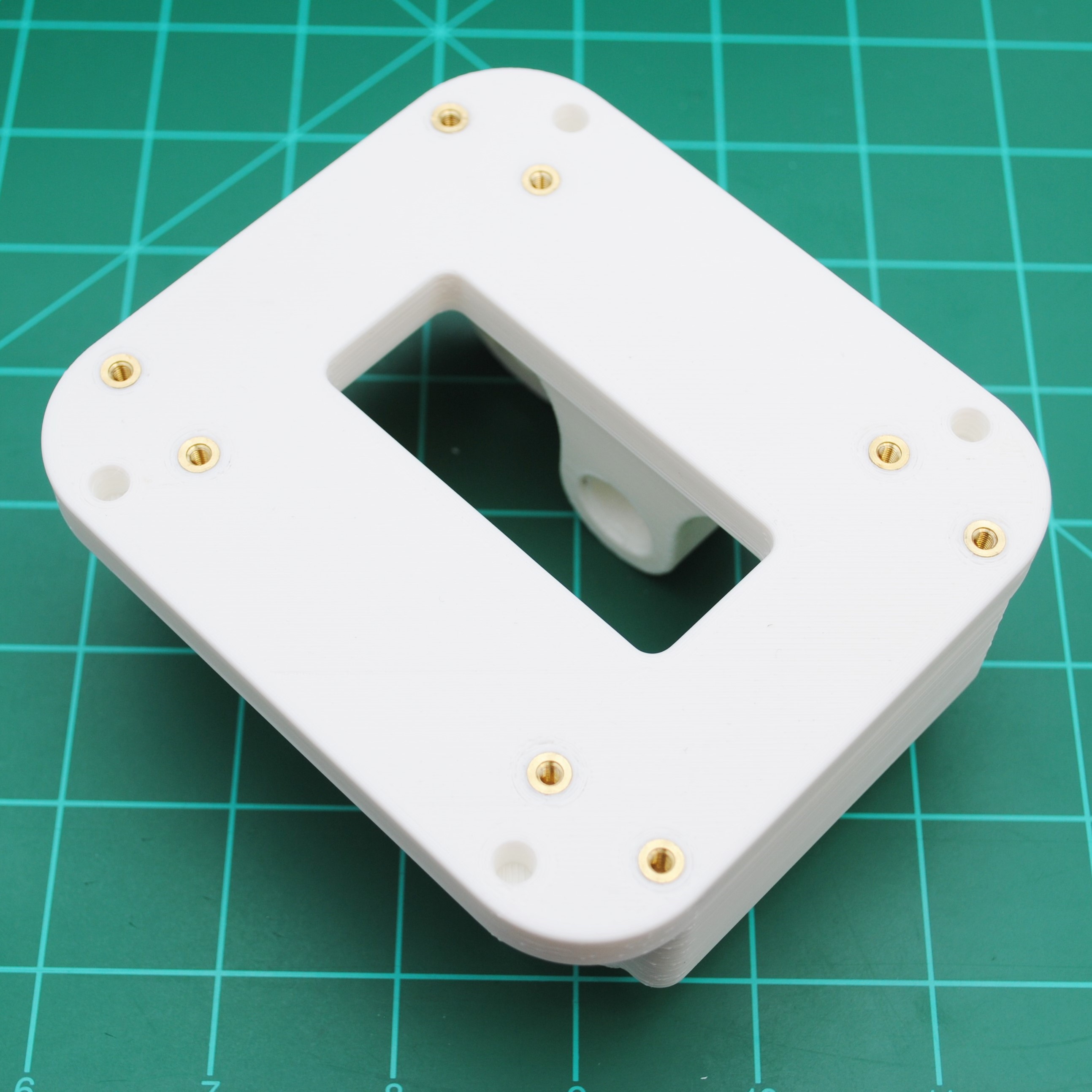
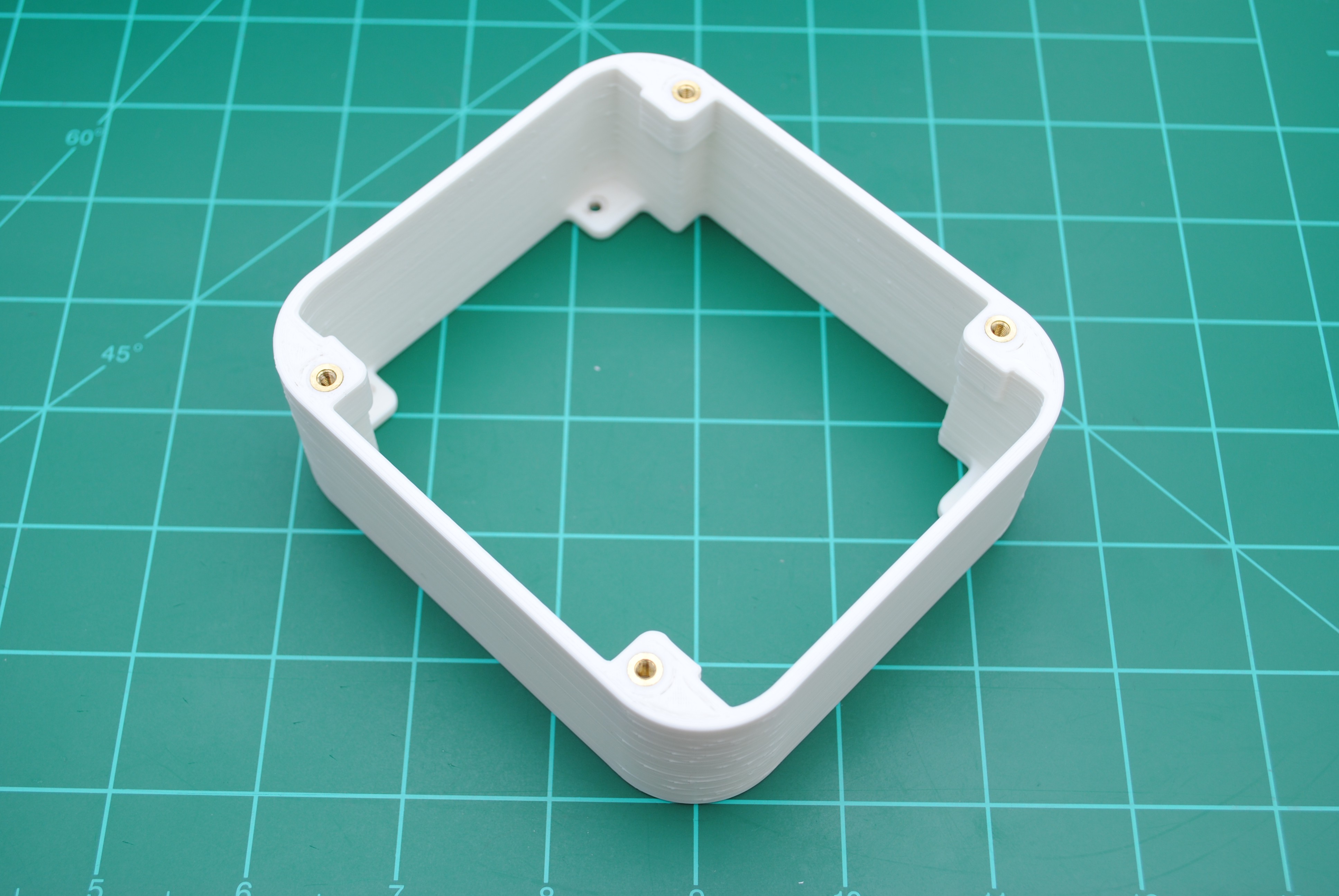
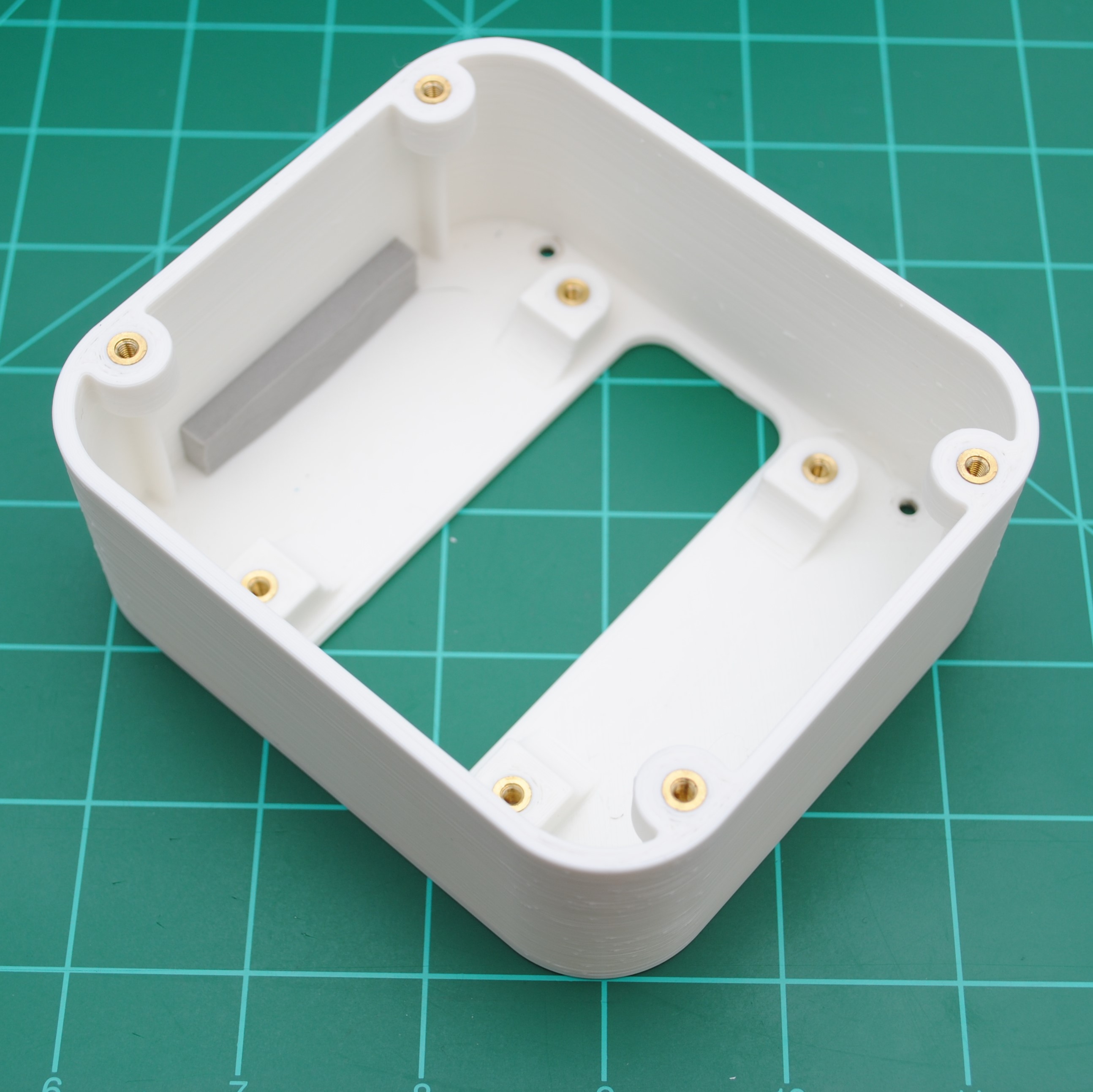
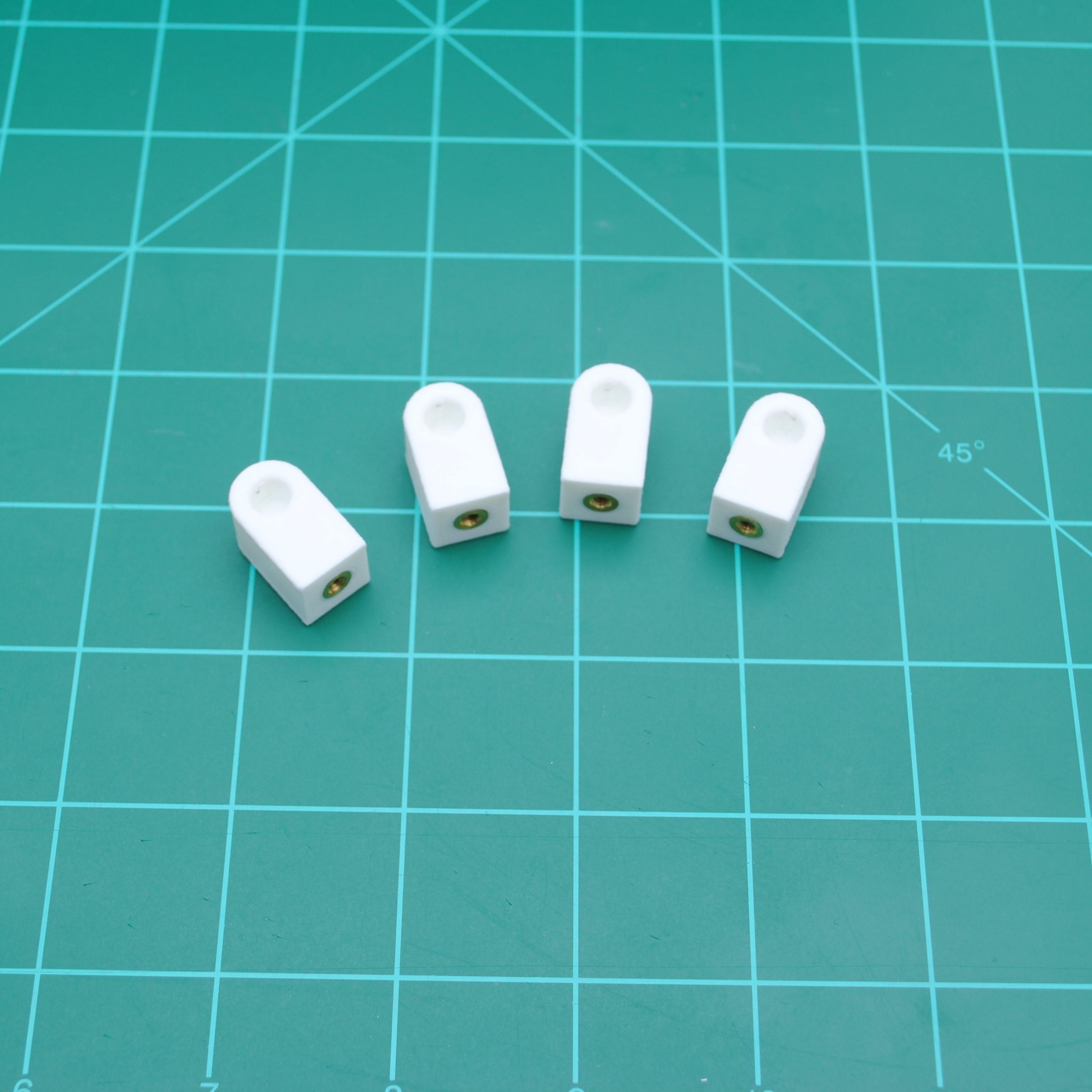
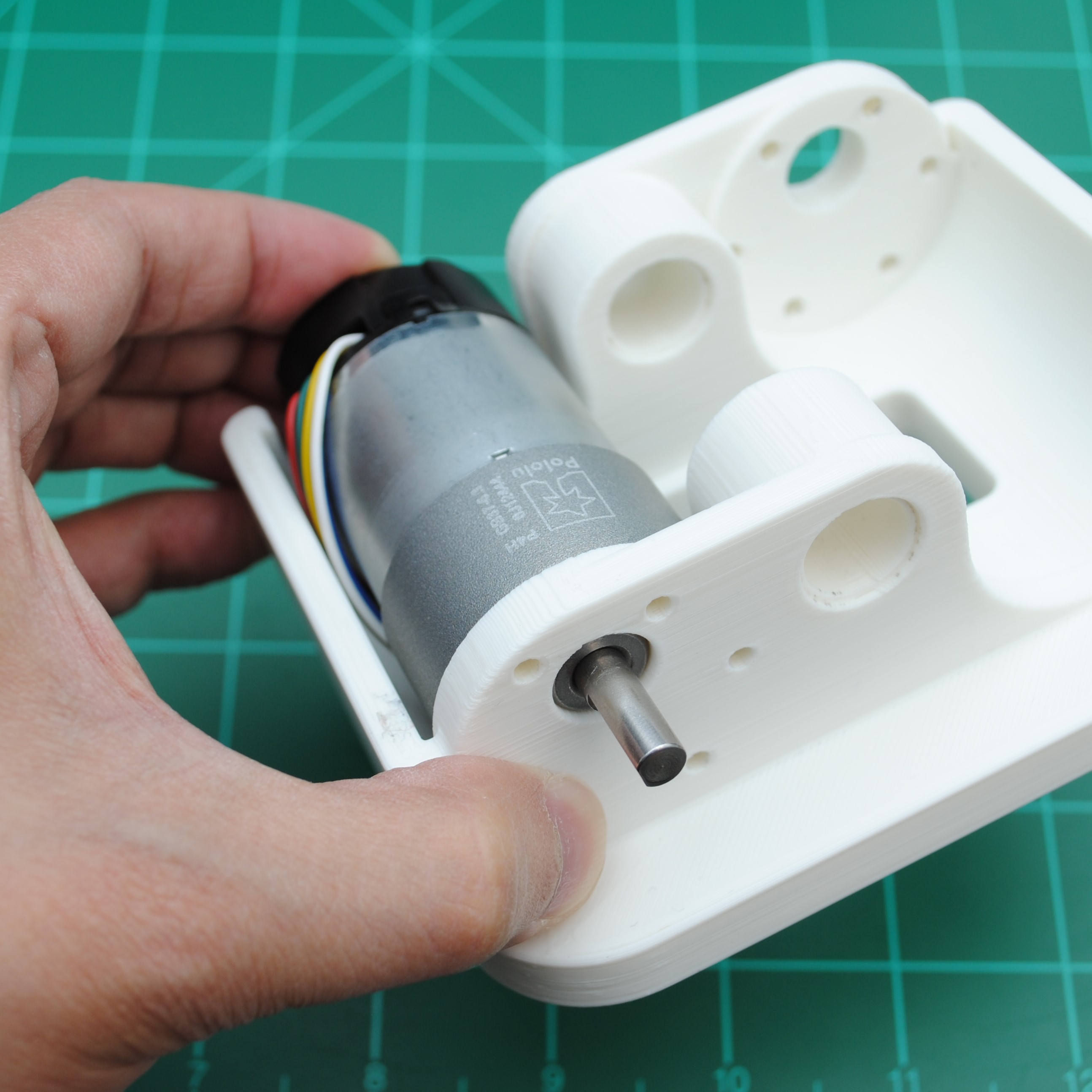
 3D Printed Components
As mentioned earlier, the structure of the robot is made out of 3D printed parts. All 3D components are available on Thingiverse: https://www.thingiverse.com/thing:4685054...
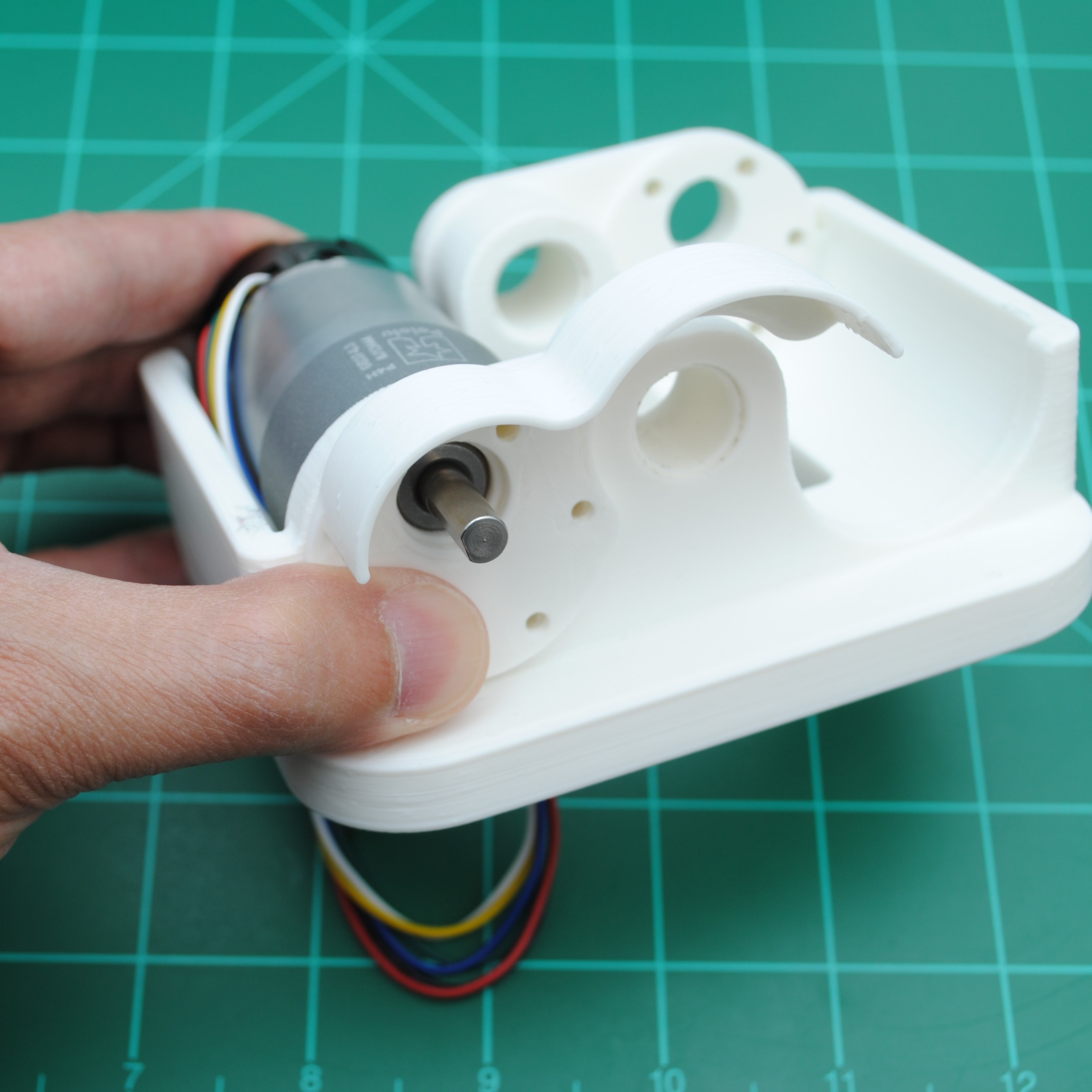
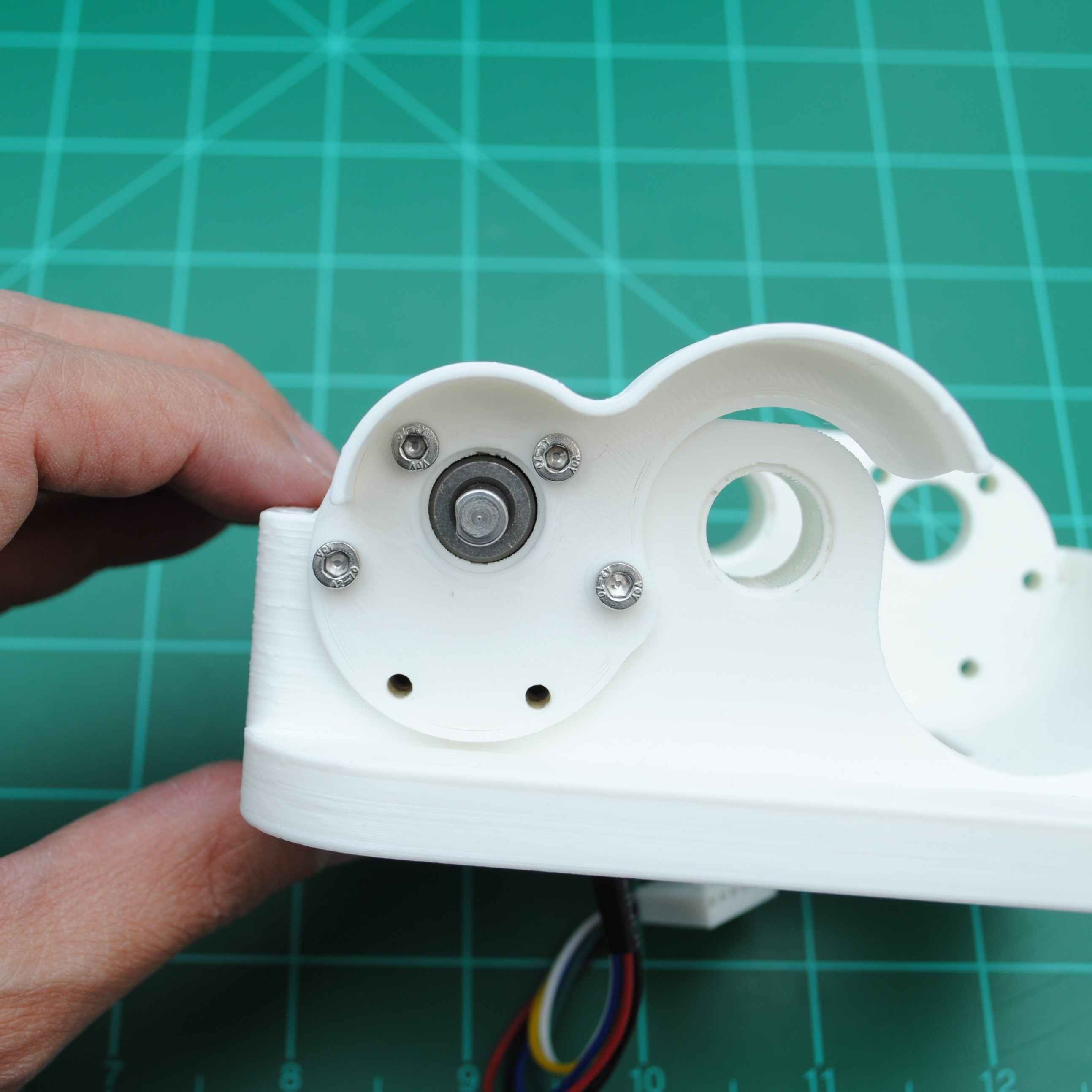 Repeat for the other side.
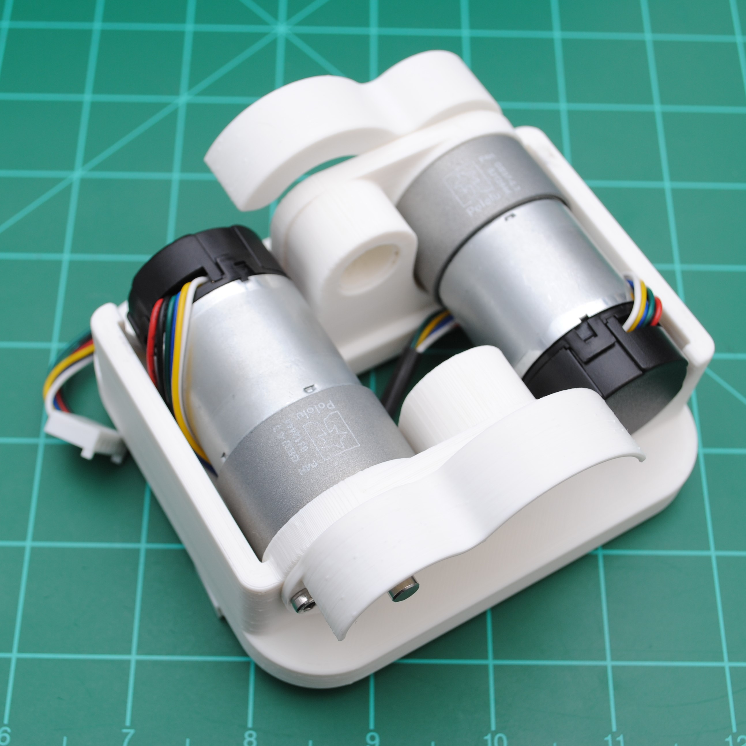


 Sean Hodgins
 NotBlackMagic
I really like this robot. We did the opposite: we tested DC motors but the lack of precision made us choose stepper motors instead (regular NEMA17 in this case). The current drained is controlled via the A4988. This is the stepper motor self-balancing robot: https://youtu.be/d6J0ijMG3jI?t=18 (And assembly guide if anyone interested: https://www.jjrobots.com/b-robot-evo-2-assembly-guide-v1-2/)