 Clyde Shaffer
Specs:
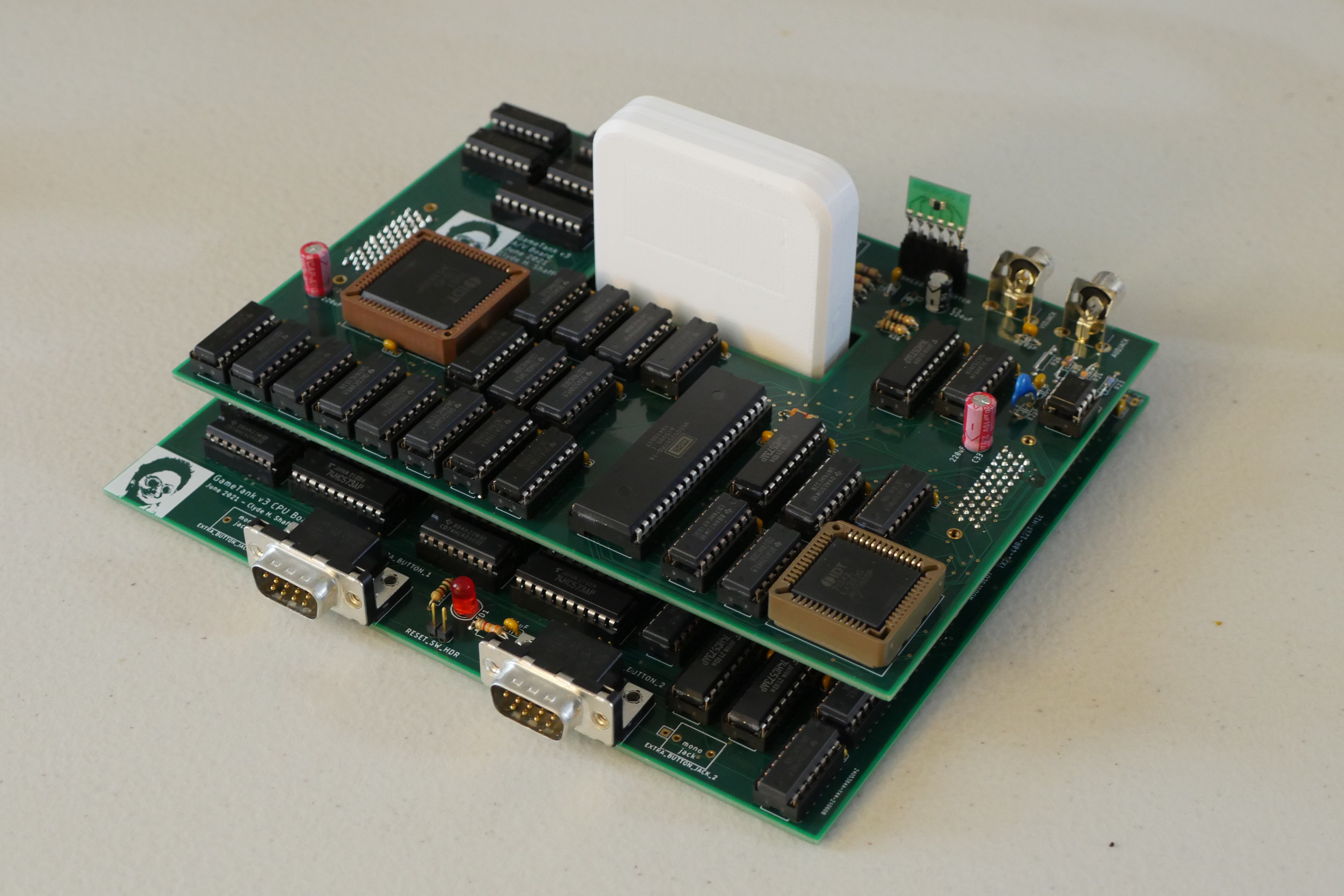
- Dual 128x128 framebuffers, 128x100 visible onscreen
- NTSC Composite video output
- Fast 1 cycle per byte hardware blitter
- 8KB of RAM
- CPU clock at 3.5MHz
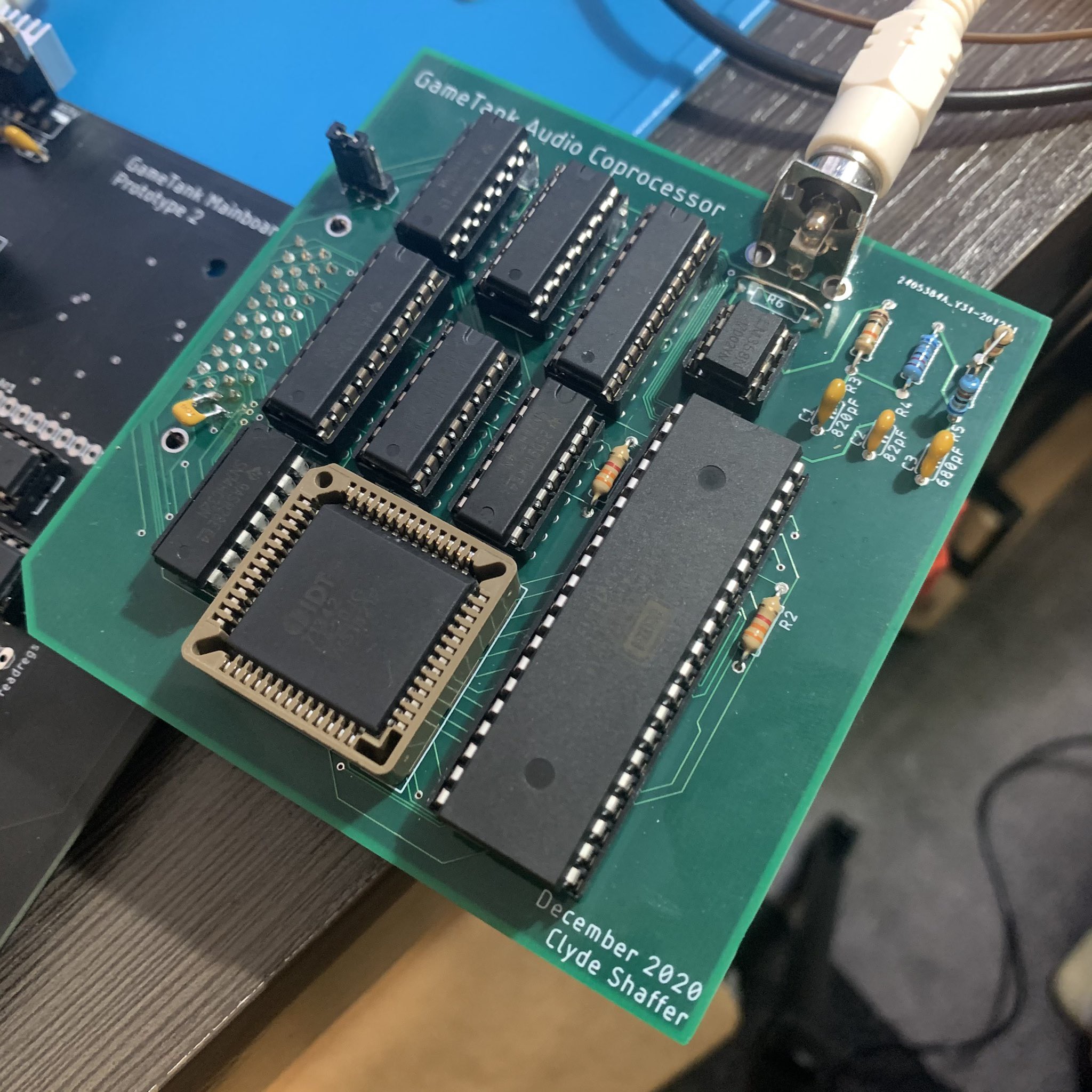
- Audio Coprocessor controlling an 8-bit DAC (second 6502 running at 14 MHz)
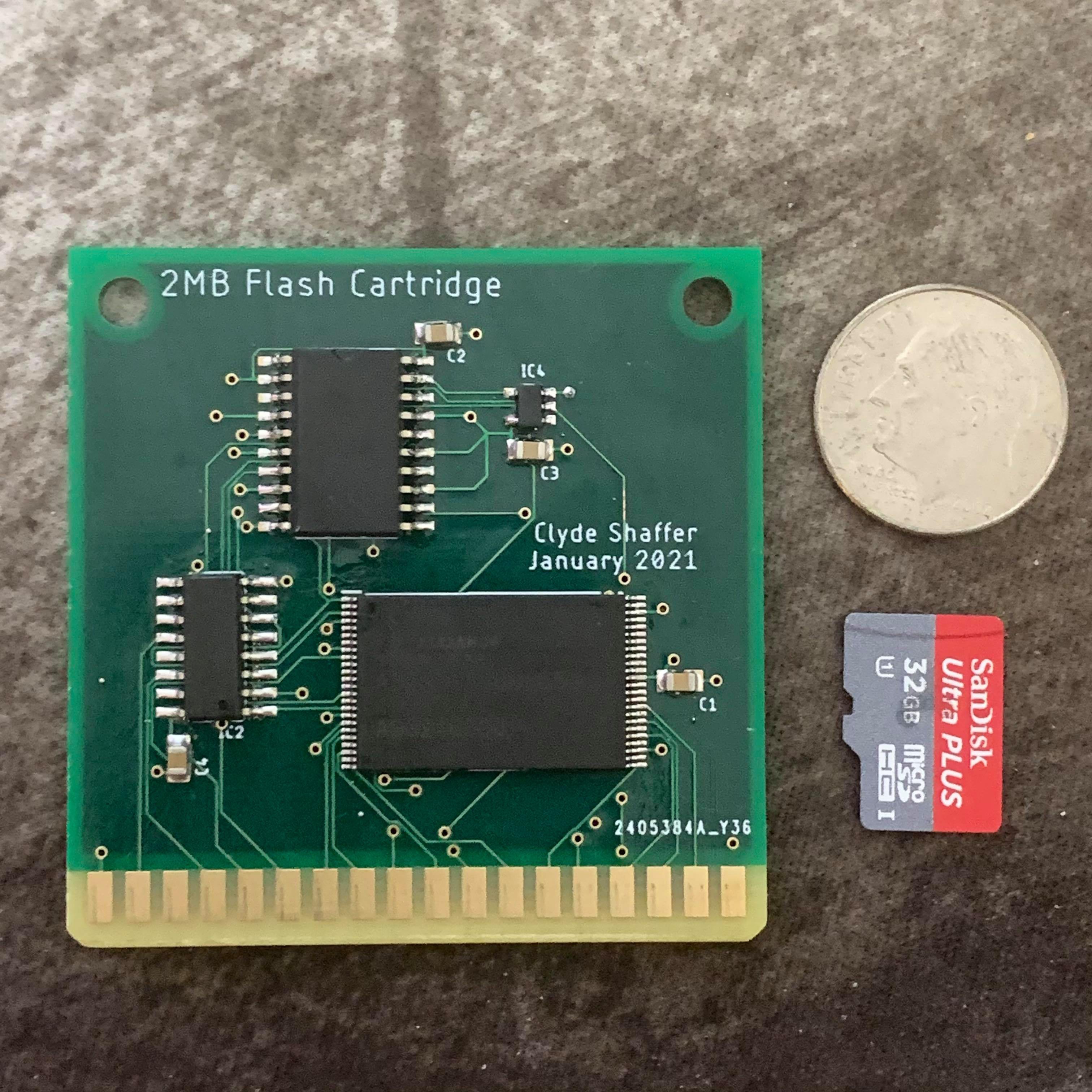
- Cartridge/expansion port that exposes the system bus, as well as a SPI port
- 32KB of address space allocated to the cartridge port
- Controller ports compatible with Genesis controller
Much of the GameTank is fairly typical of a W65C02-based retrocomputer project, but it does have a special trick up its sleeve. The composite video signal generator uses a dual-ported RAM as a framebuffer, and between the CPU and framebuffer sits a dedicated memory copy controller that can copy bytes into VRAM without the overhead of a software-defined copy loop.
Additionally, sound is now generated by a second 6502 programmed through dual-ported RAM, which controls an 8-bit DAC. A programmable interrupt generator and a latched buffer allow this coprocessor to generate samples with consistent timing.
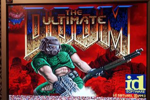
At this time an online version of the emulator is now available, along with an example project written in C using the cc65 compiler.
The online emulator includes four hosted demos, and can also load ROM files from the local machine:
https://gametank.zone/games/
The EAGLE design files, the emulator, some software for the system are on my Github:
https://github.com/clydeshaffer/gametank
https://github.com/clydeshaffer/GameTankEmulator
Platforming game written in assembly:
https://github.com/clydeshaffer/cubicleknight
Tetris clone written in C:
https://github.com/clydeshaffer/GameTankTetris
Roguelite written in C:


 Matt Stock
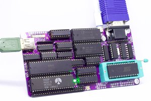
 Anders Nielsen
 Marcel van Kervinck
 Mars
Mars