 Mario Ninic
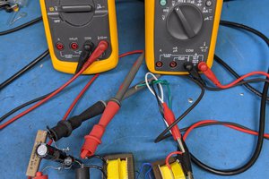
Modification procedure (see schematic diagram posted with the pictures).
- Remove plastic cover from the back of the meter.
- Remove diode D1 and Inductor L1. The internal supply should be out of the circuit now.
- Identify common ground or negative power supply line (point B) and mark input connector.
- Solder + 12Vdc power supply to the (point A) or to the input terminal of the 7805 regulator.
- Connect -12Vdc power supply to the point B marked at the step above.
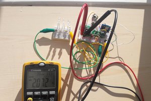
- At this point you can turn on 12Vdc power supply and power meter should be on. Do not connect AC input at this point, this step is just to verify proper operation with the external supply. If display works correctly you can assemble it back in original case.
- Isolate external 12Vdc supply. The terminals should not be exposed.
- Connect the AC measurement terminal. This meter should measure from 0Vac to 300Vac.
DANGER!!!
This modified circuit should be used only with isolation transformer.
 Denis
Denis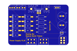
 Hamza Deniz Yılmaz