 Nathan Kerns
I started this project only a week or so ago, after seeing this video about the concept. I started designing a circuit to replicate the one in the video, using a transimpedance amplifier to process the signal and maybe another op amp to amplify the signal a bit. The problem I had was trying to find an appropriate laser diode, one with the photodiode built in. There were a few on Digikey, but mostly in IR, which wasn't a great option since the beam wouldn't be visible. That's a problem for safety, makes it harder to work with, and simply doesn't look as cool. Thorlabs had a lot more options, and this one looked best to me. Still, it's about $15, which is not expensive but also not cheap for a single component. I just happened to be using some cheap laser diodes for another project, and noticed that they had a little gap in the back that allowed some of the light through. I could attach a photosensor there and have something that's functionally the same, though probably not as precise.
I started off with a photoresistor, since that's all I had on hand, and hot glued it to the back. The entire assembly was then wrapped in electrical tape to try to prevent any light from getting in and affecting the results. This prototype worked to an extent, producing a signal that was mostly noise, but appeared to have some evidence of interference. The signal was way too noisy to be of any use, though. The problem seemed to be with the choice of sensor. The standard CdS based photoresistor was extremely slow, having a rise time measured in tens of milliseconds when the signal I was trying to measure was in the tens of microseconds. It would not be good enough for anything beyond a proof of concept.
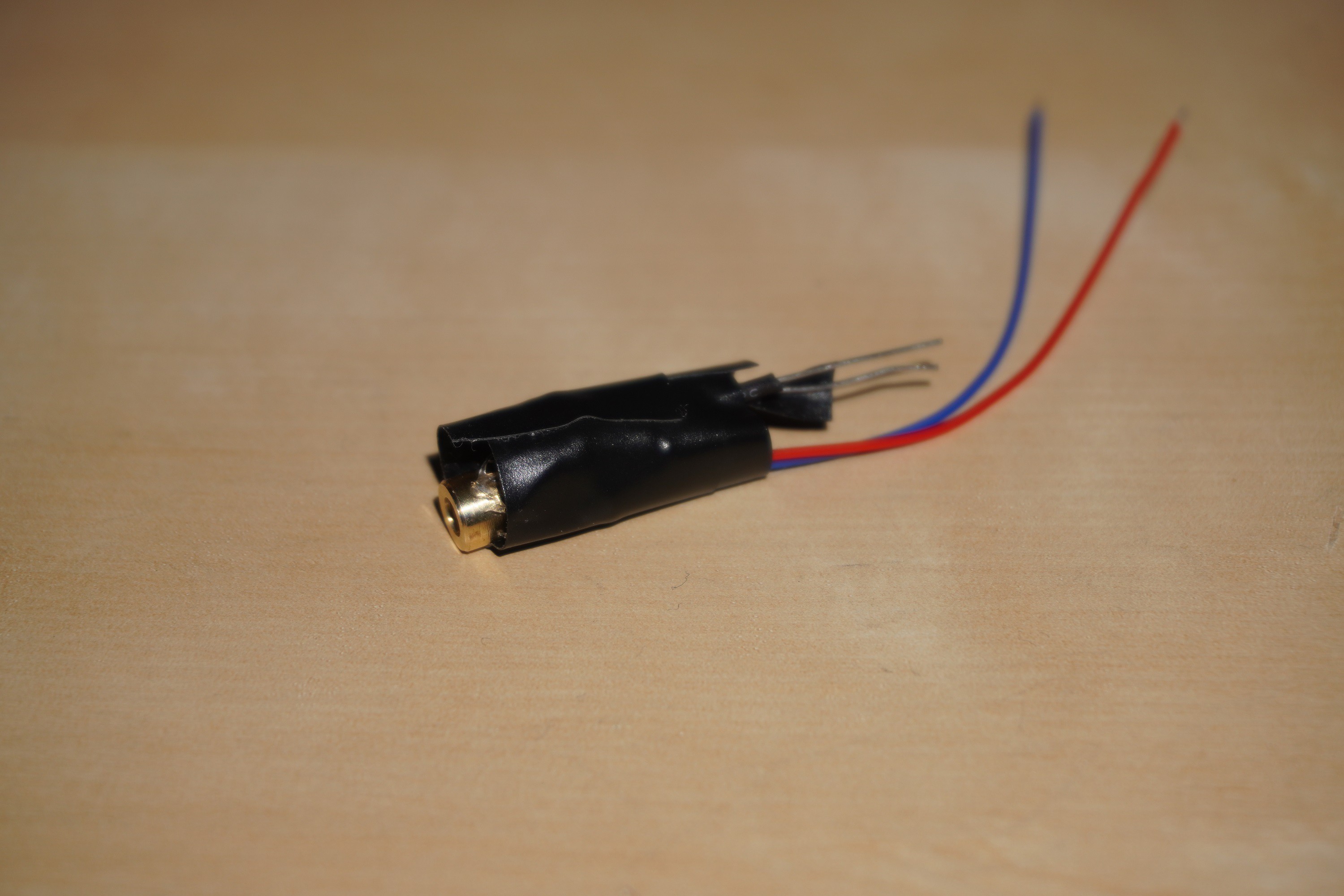
The first prototype I made. A little too much hot glue was used, causing the tape to not create a good seal against light.
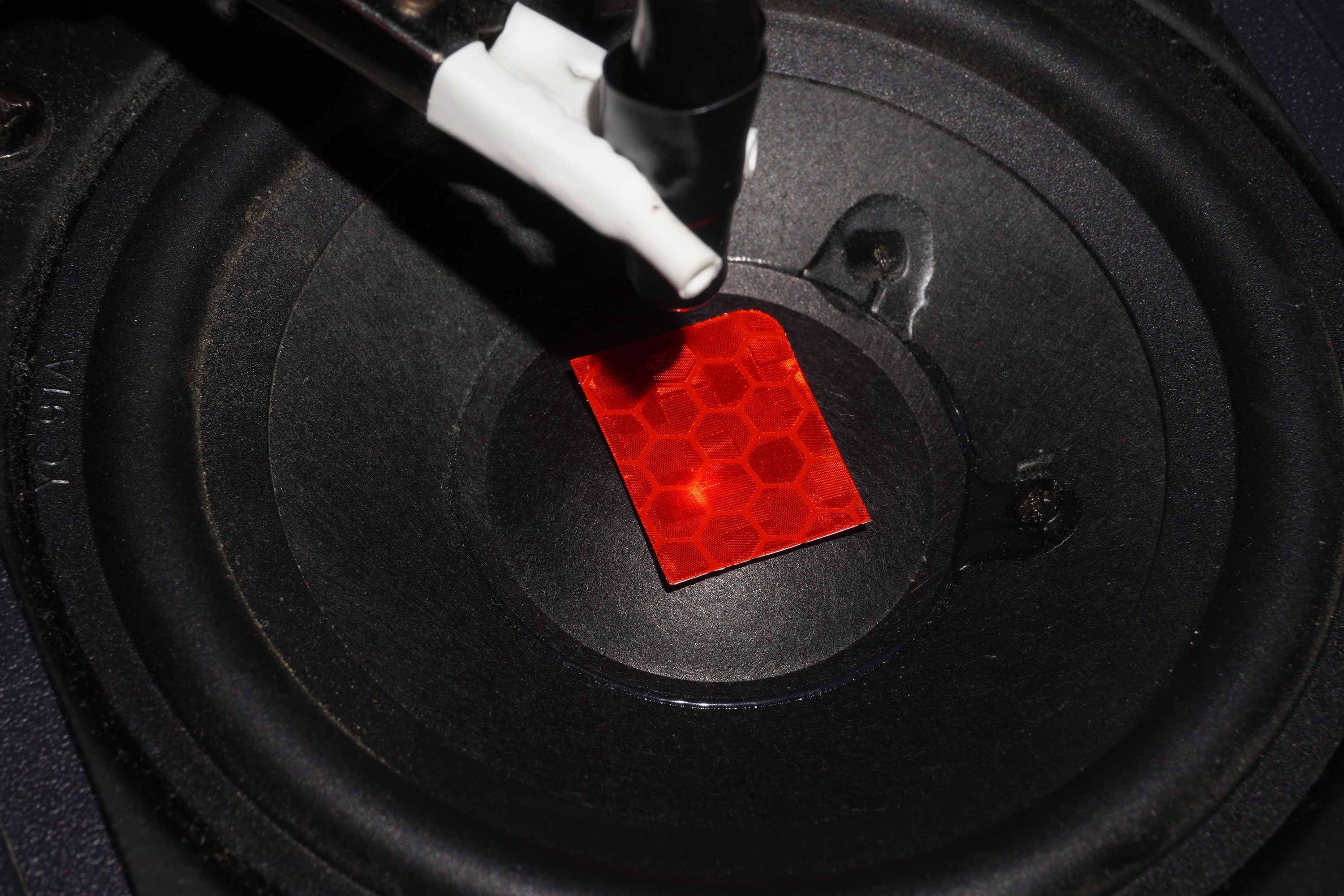
The test setup. The laser points at a piece of reflective tape, attached to a speaker outputing a low frequency sine wave at a very low amplitude (imperceptible by sound or touch).
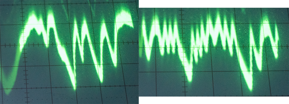
Two samples of the signal from the first prototype. It's not very clean, but the interference is definitely there, especially in the second image.
Two other types of sensors were available to replace the photoresistor: phototransistors, and photodiodes. There's a few differences between the two, the most important being that photodiodes have a faster response time and more resources available online detailing their use. But the both work in about the same way, turning photons that hit them into current. I'll admit, I didn't consider any of this when I bought some. I just got the cheapest pack on amazon that had 2 day shipping, which turned out to be phototransistors (but where advertised as photodiodes - one of the product reviews pointed this out). When those arrived, I made pretty much the same thing as before, but I had to file down a notch in the phototransistor to get it to fit better. I used a lot less hot glue this time, and managed to create a better seal. When I tested this version, the signal was significantly better, very close to the signal shown in the video and in papers:
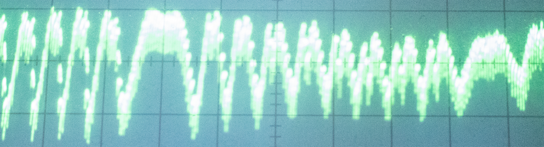
A signal from the second prototype, showing clear interferometric fringes.
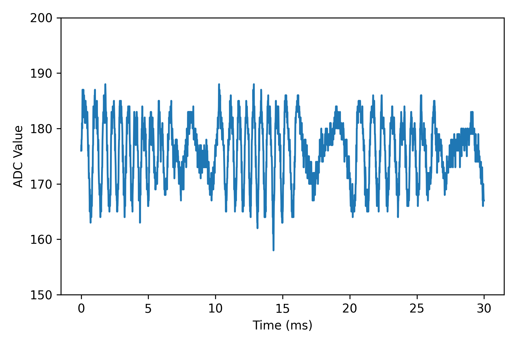 A digitized signal, captured with the ADC on a Teensy 4.0 and graphed in Python. The signal is much cleaner due to the filter on the laser power supply.
There's still a lot of high frequency noise in the signal, which turned out to be from the 5V AC adapter I was using which had a switching frequency of only 10 KHz. This was easily fixed with a RC LPF circuit in between the power supply and the laser. Otherwise, this signal looks pretty good. I can easily count the number of fringes, so since the laser has a wavelength of 650nm, it works out to a distance of around 3 um (I believe each peak corresponds to half a wavelength of movement, or one wavelength over the entire path, but I need to do more testing to confirm this). That means the speaker is moving back and forth only a few micrometers, and it's easily detectable with something I've made from $1 worth of materials (and about $50 of other miscellaneous equipment). As far as I can tell, this makes it the cheapest interferometer ever built, and probably the worst as well. Regardless, I want to see what can be done with it. My next goal is to continue working on digitizing the signal and processing it in python. I've already got a Teensy 4.0 set up capturing data with the ADC and sending it over serial to a python script, but I need to learn more about DSP to get useful information from the signal. The analog front end currently consists of a voltage divider and an op amp acting as a noninverting amplifier, as well as a few RC filters. There's definitely room for improvement there. Then, I need to do some calibration to compare it to something I can measure the movement of on a macro scale, such as attaching it to the Z axis of my 3D printer and jogging it up and down very slowly. After that, I want to use it for a few experiments, like measuring the universal gravitational constant or measuring vibrations and sound. It might even be possible to observe the Sagnac effect, if I can get my hands on enough fiber optic cable. If anyone has any other suggestions or ideas, let me know.
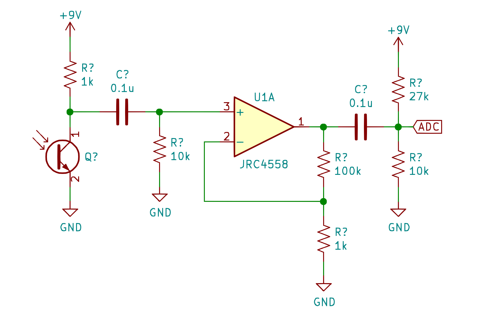 The analog circuitry that filters and amplifier the signal. This was just thrown together to get results, there's plenty of room for improvement.
Discussions
Become a Hackaday.io Member
Create an account to leave a comment. Already have an account? Log In.
Cool project, love how you made the project work without having to depend too much on the internal wiring of the laser diode
It's been like 4 years but if you ever do revisit the project, I'm wondering if it might be possible to get 3 or more of these photodiodes in a row then you would be able to count the steps to get somewhat stable absolute distance.
The idea is if you have 3 of these 1, 2, 3, if something moves forward 2 would spike and if something moves backwards 3 would spike, so depending on the last spike and the current spike you can tell if something moved forward or backwards.
Don't know enough about measuring though so this might be a completely silly idea depending on how difficult it is to measure and synchronize the three diodes.
Are you sure? yes | no