PCB Assembly
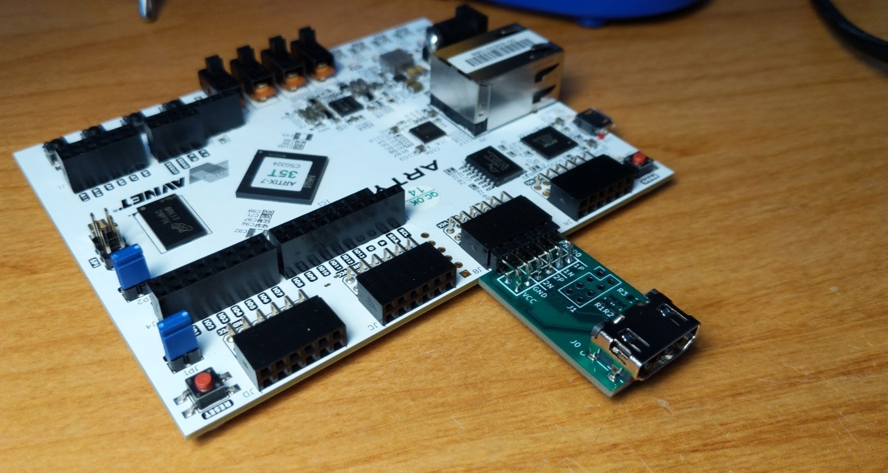
The PCBs that I ordered came in this week, and they look nice! I am surprised at how tiny they feel compared to how they looked on my monitor. An assembled PCB plugged into my Arty A7 board is shown below. I didn't solder the header or resistors connected to the sideband signals, since I'm not planning on using those yet.
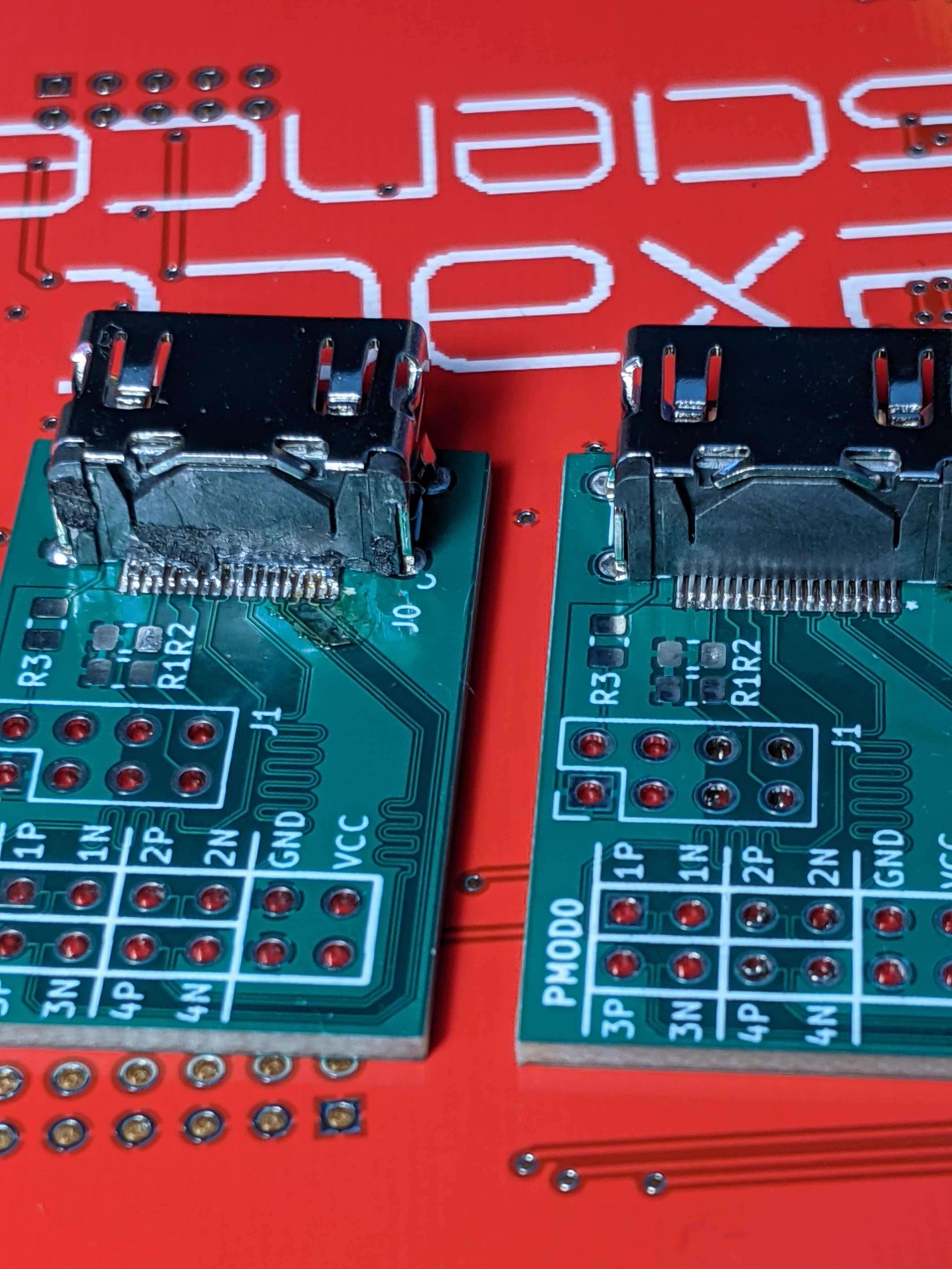
Admittedly it took me two attempts to get the HDMI connector soldered down correctly. I have a Hakko FX-888D iron which works well enough, but a hot air station and some solder paste would have definitely helped with the 0.5 mm pitch pins on the HDMI connector. I tried doing it the quick and dirty way the first time around by swiping across all of the pins, and then cleaning up with some solder wick. You can see how well that turned out below.
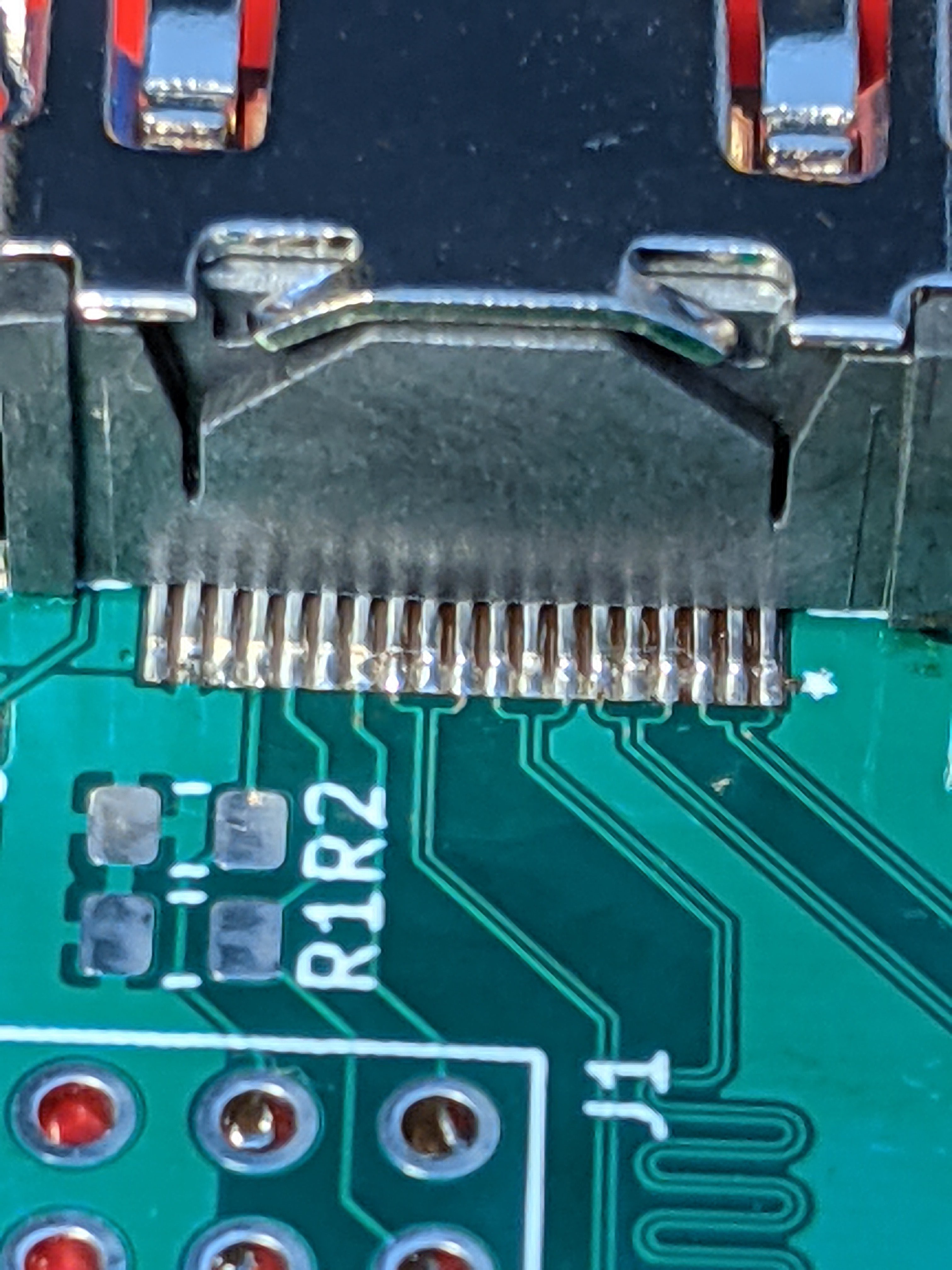
On my second attempt I applied some flux to each pin, and then hit each one individually with a tinned iron. This still required some cleanup with the solder wick, but the result is much prettier. Here's a closeup.
OpenEMS Simulation Progress
I did spend a weekend trying to import the PCB into OpenEMS, but ran into some problems with the tools I tried. I first tried pcbmodelgen, which converts Kicad PCBs into an Octave/Matlab description of the geometry the mesh needed for simulation. While the examples worked fine for me, I couldn't figure out how to make it work with four layer boards. Next I tried pcb-rnd. It has a plugin for reading Kicad PCBs, but I think the version of Kicad I am using is too new for it. Upon importing my PCB, it puked with a message about the file format being unrecognized.
For Gentoo users, I created ebuilds for both pcbmodelgen and pcb-rnd, which you can access here and here. The pcb-rnd ebuild is pretty lazy, and could have been done better had I taken the time to learn the project's replacement for autotools.
I still plan to do a simulation at some point, but it will require some more work. I think the route forward will require that I either make changes to pcbmodelgen or roll my own tool. Whichever way I choose will probably warrant its own post, so stay tuned here for any updates.
Next Steps
Testing the PCB is the next thing in the queue for me. I'm hoping I can simply load up the project from Domipheus Labs and hit go. Once that's done, I will work on writing my own module in Verilog and packaging it up with FuseSoC.
Discussions
Become a Hackaday.io Member
Create an account to leave a comment. Already have an account? Log In.