 Bob Baddeley
The situation: There's a kid outside playing, and they want to show you something. You are in the middle of an important meeting while working from home. You need to indicate that you are not to be disturbed at this moment.
The purpose of this project is to solve that problem by creating a status indicator that is visible outside the room. I used components I already had lying around the house, and the number of components is very small and easily adapted to what you have available.
The power supply was USB because it was a quick and easy way to get DC power. While you could run this off a battery, and it would last a long time, I decided to go for something longer lasting. I happened to have a connector (USB-B connectors typically have through hole pins, so they're easier to solder than USB-micro or mini). You only need the VUSB and GND pins, and it's simple to probe with a multimeter on a powered USB cable plugged into the connector to figure out which ones are which.
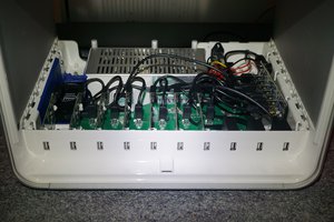
The enclosure was a leftover from New Age Enclosures, but anything would work, including a mint tin or yogurt container or whatever. You need to poke a hole for the power cable, holes on top for the LEDs and a square hole for the switch, as well as a hole for the outgoing wire.
Inside is a very simple circuit. The ground is shared to the LEDs, and the power goes to both center poles of the switch. Each of the other poles goes through a 330 Ohm resistor to the LEDs. I used a Double Pole Double Throw (DPDT) switch because it let me control two circuits on each switch, though in this case a single pole would have worked identically. Since the power goes to both center poles it essentially makes it into a single pole. This was the switch I had lying around, though, so *shrug*. Anyway, Red LEDs are attached to one side, and Green LEDs are attached to the other side. This particular switch has the ability to go Left/Center/Right, so by putting the switch in the center you can turn it off, and then flipping the switch to either side will turn on the LEDs. Components are just soldered or hot glued in place. There isn't really a need for a circuit board.
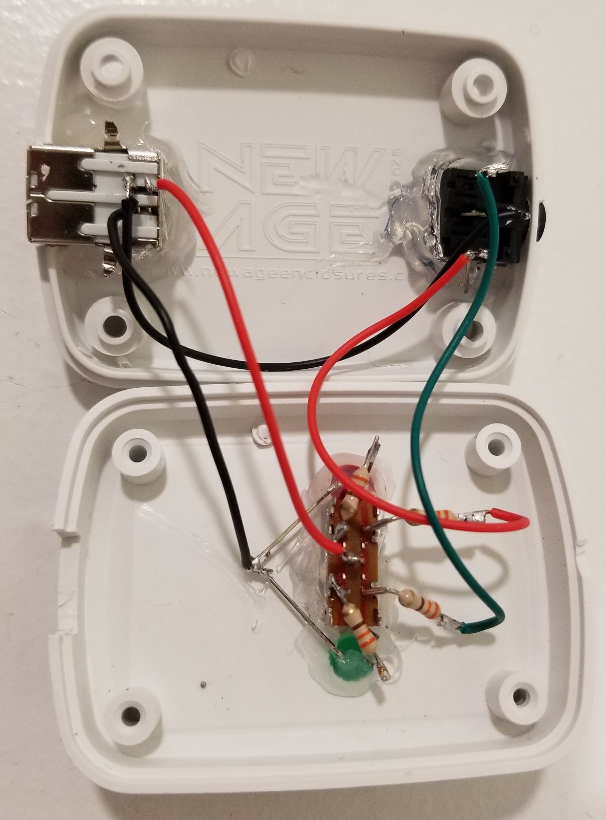
The wires go out of the switch, through the resistors, and to a stereo headphone connector, which was convenient because 1) I had some old dead headphones so I already had a cable with the right connector 2) It has the correct number of conductors 3) I have an extension cable if I need.
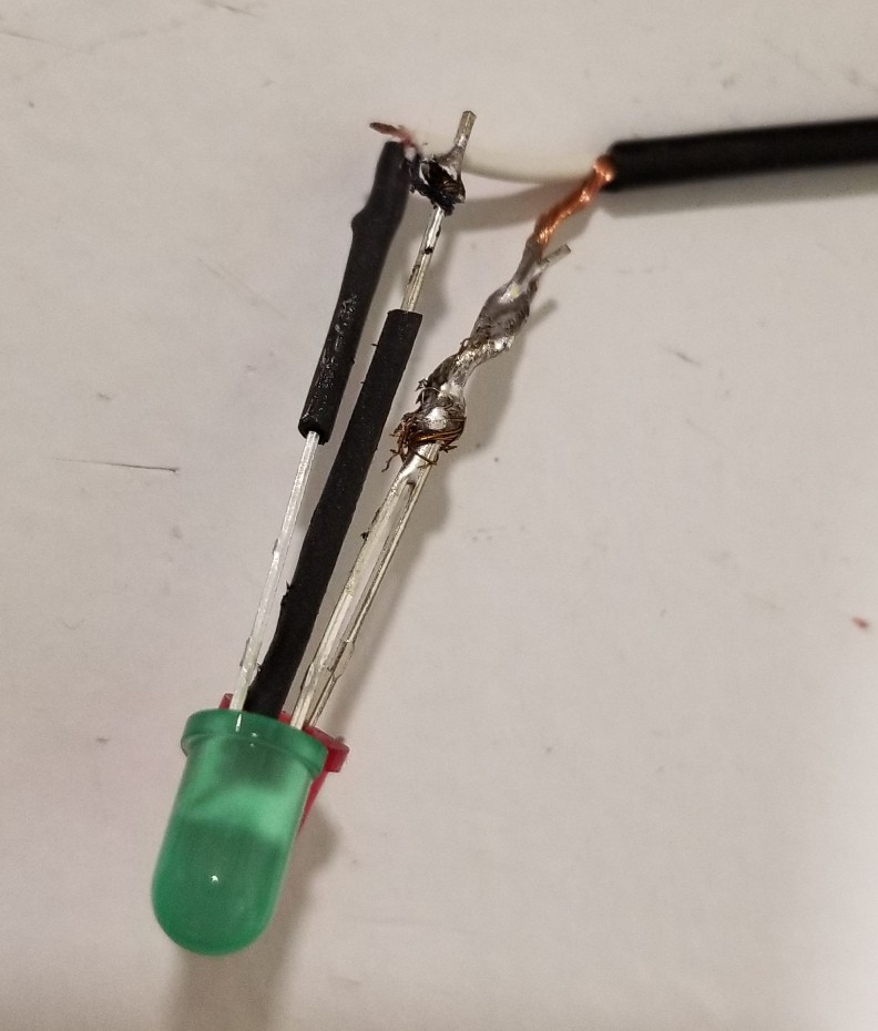
The stereo cable has three conductors, which are for ground, Red, and Green. You just wire the LEDs up on the other end, making sure they don't short anything, and clean it up to protect the wires. That's it.
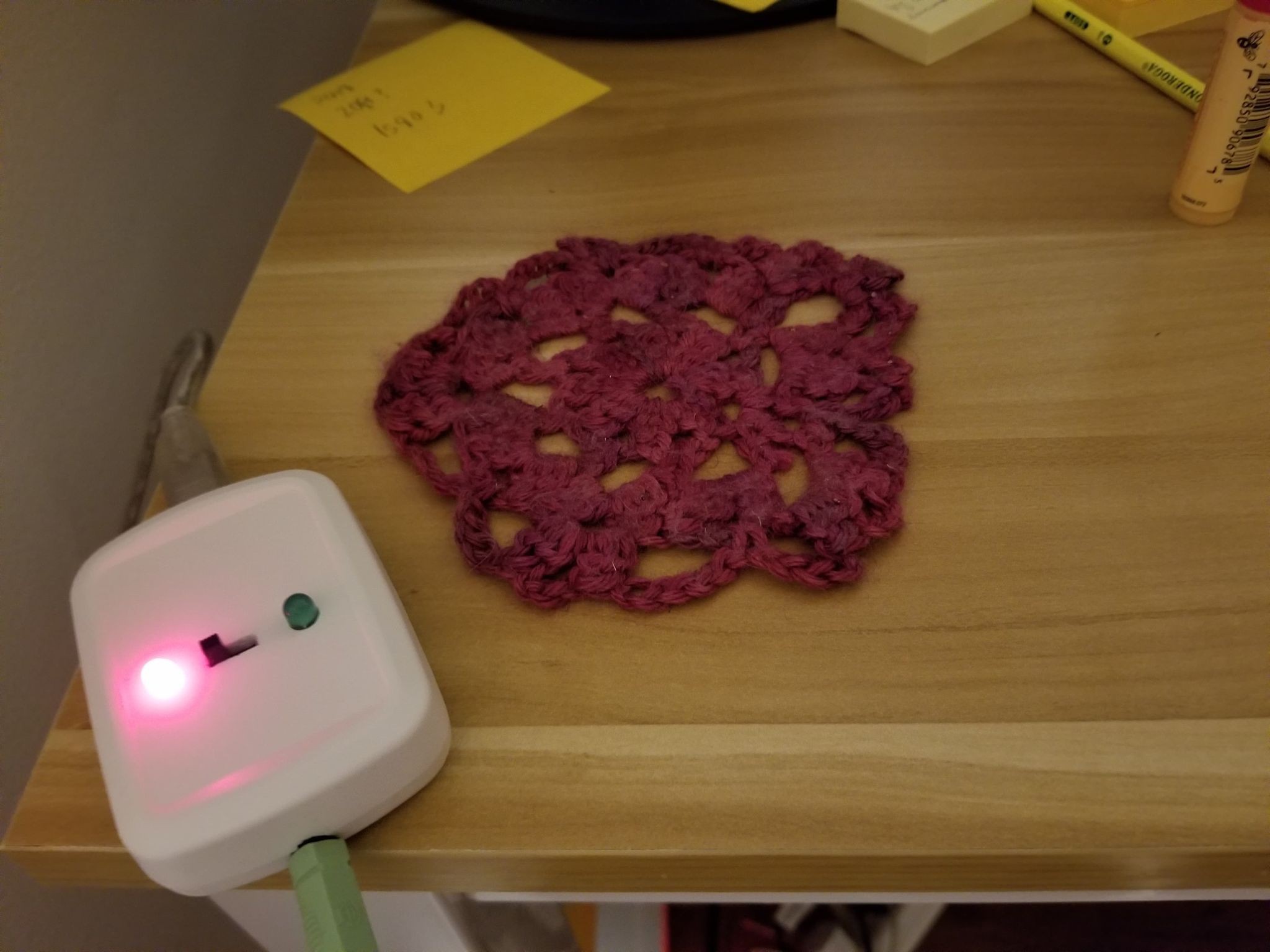
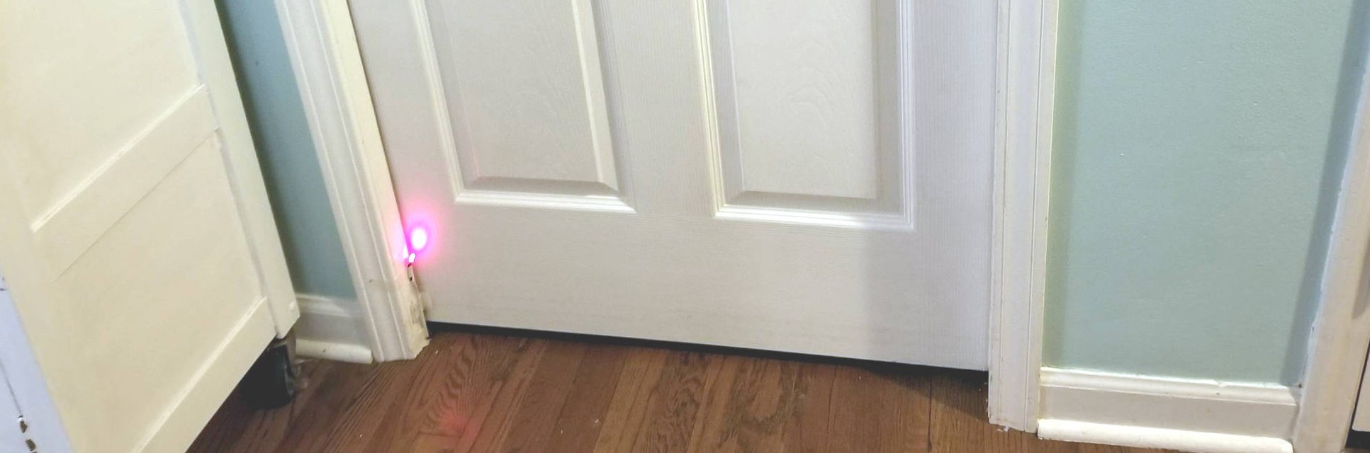
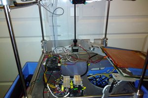
The best way to install is to have the box sitting on or near your desk so that you can see its status at a glance and change it. Without this feedback you'll forget what it is or that you need to update it, and it won't be correct and you'll get interrupted. Then route the stereo cable so that the LEDs are just outside the door. You may have the best luck going under the door near the hinge and up so that the door can open and close.
 Paul Nicholls
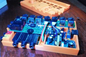
 Patrick
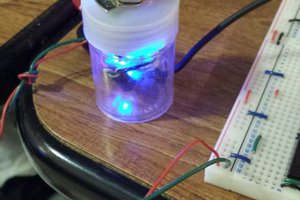
 Macrofarad