0%
0%
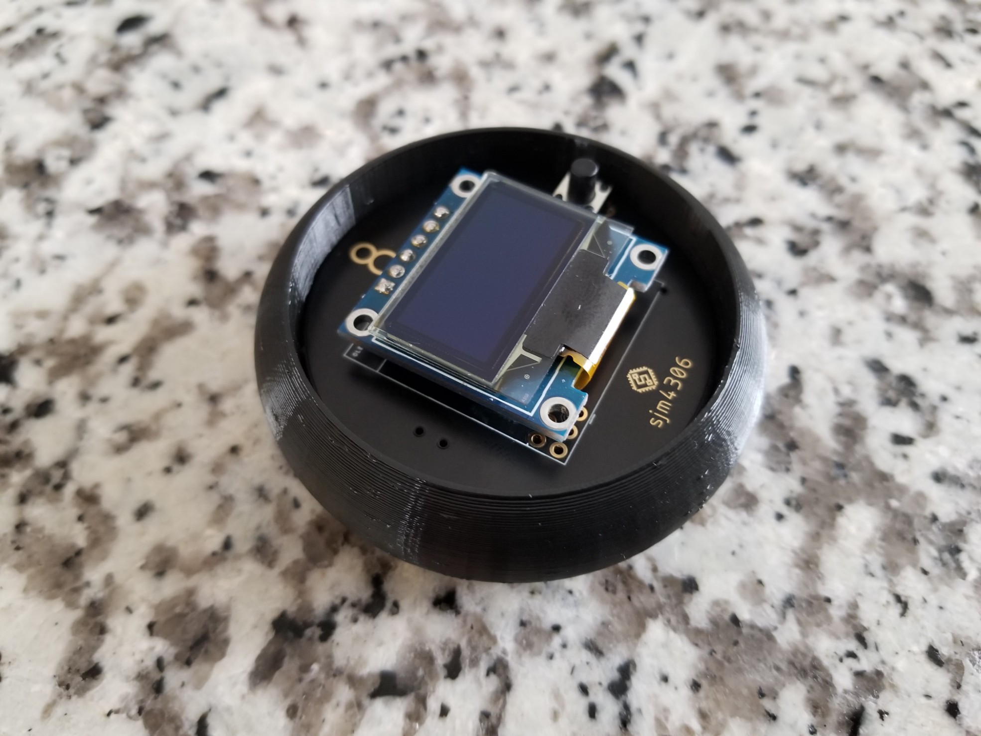
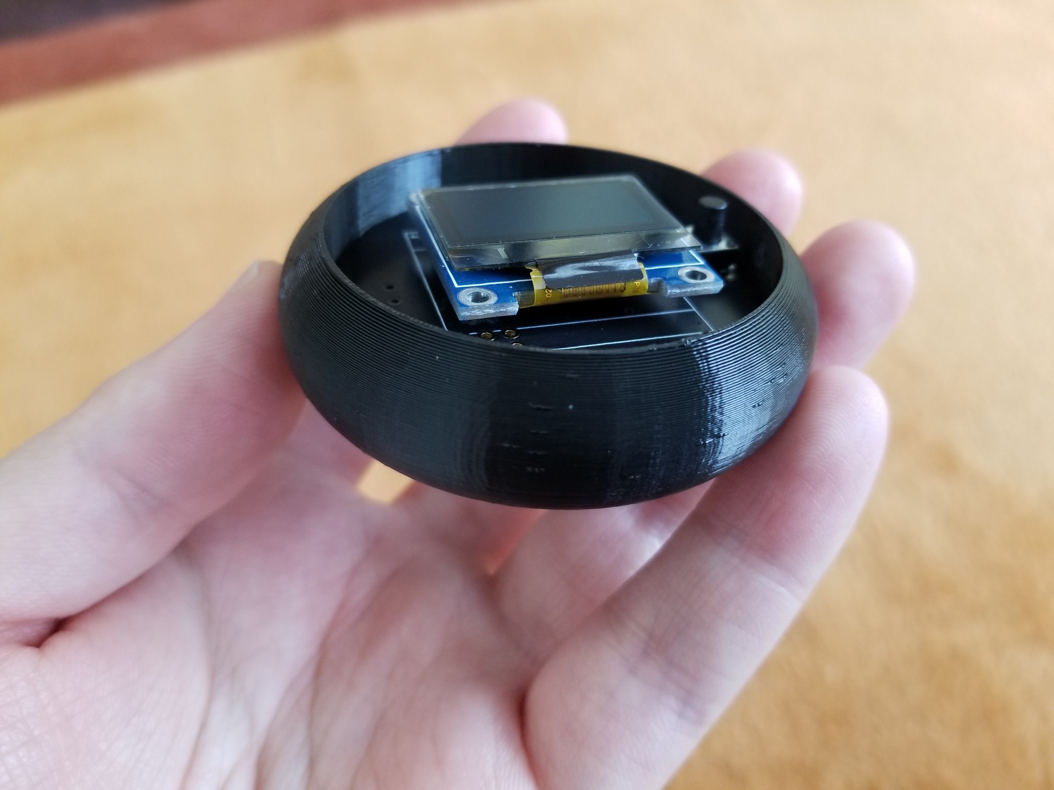
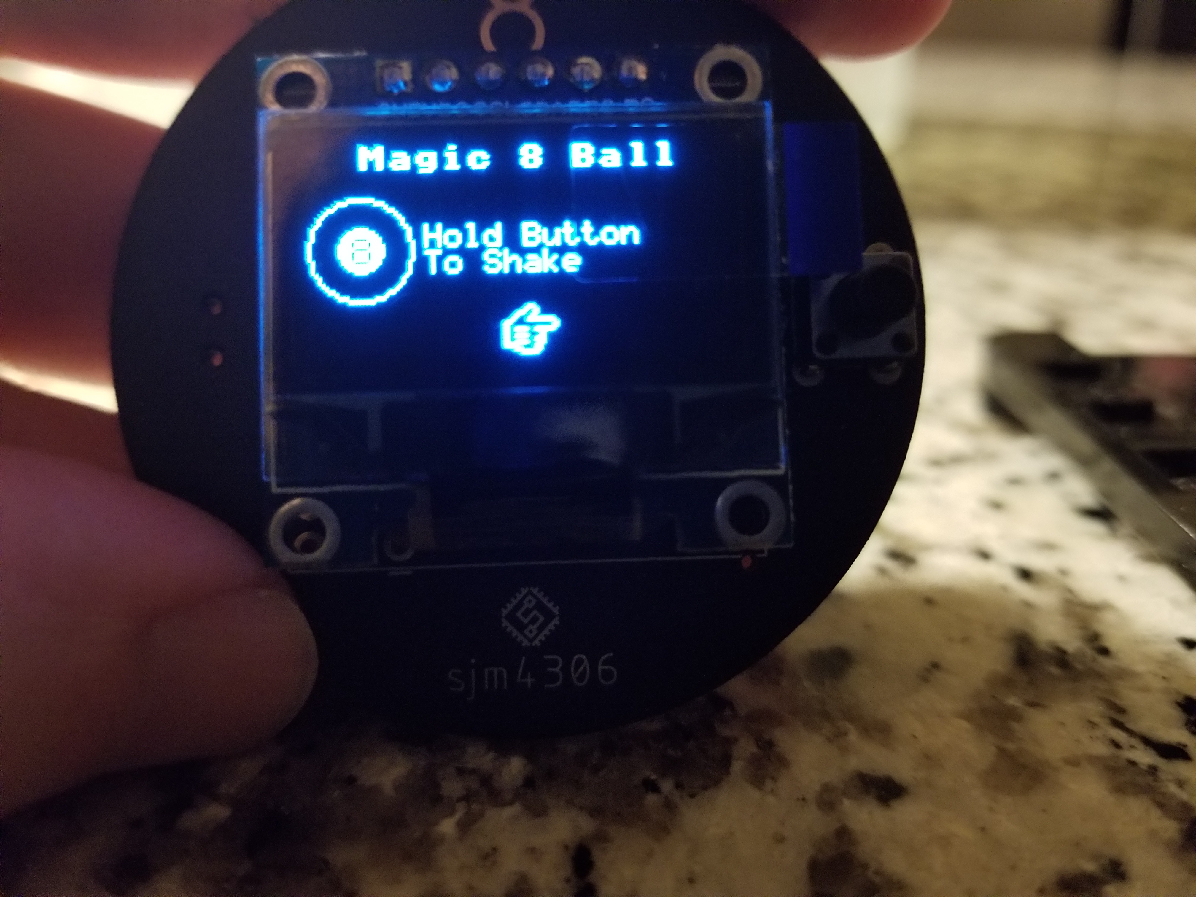
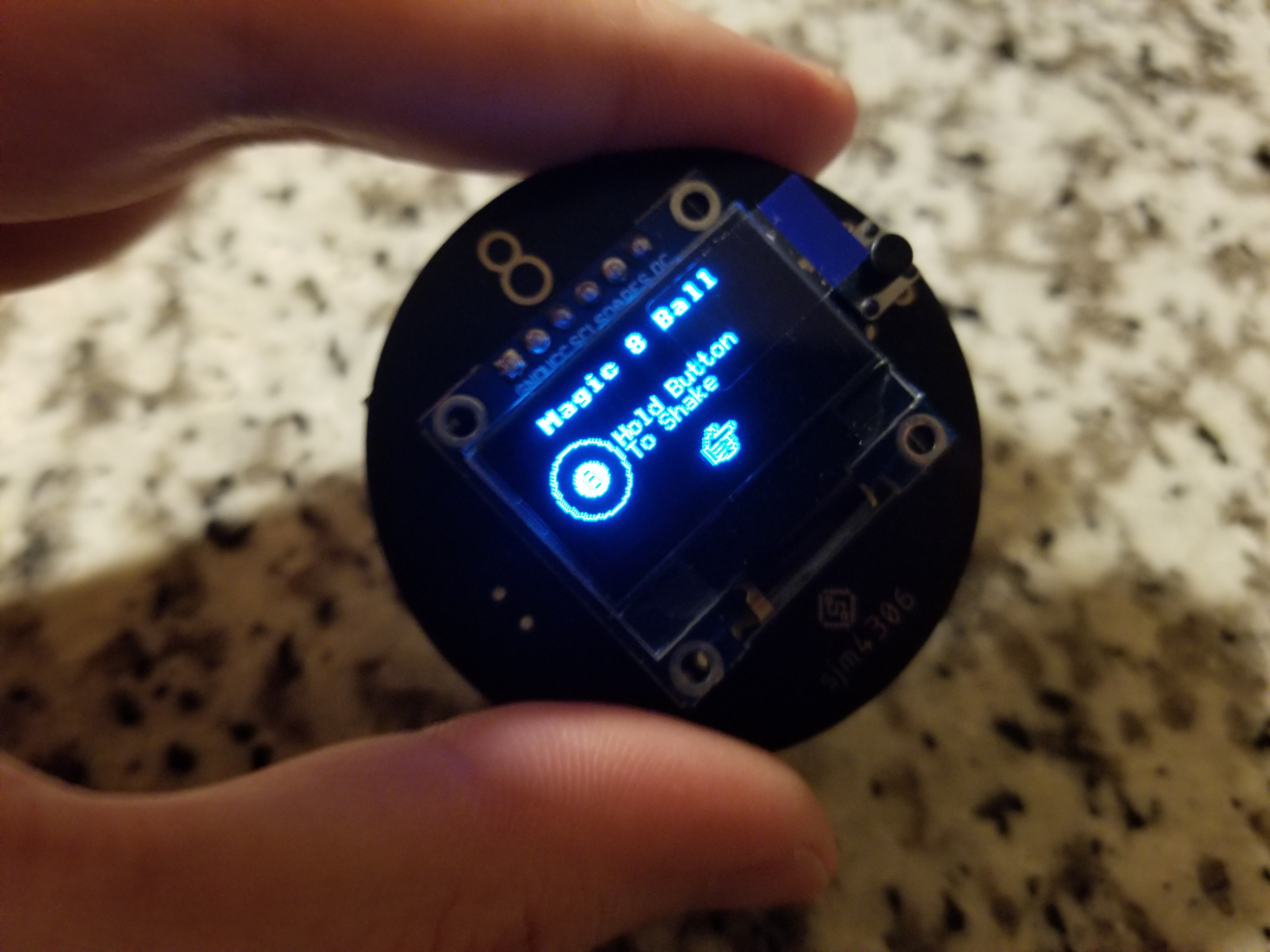
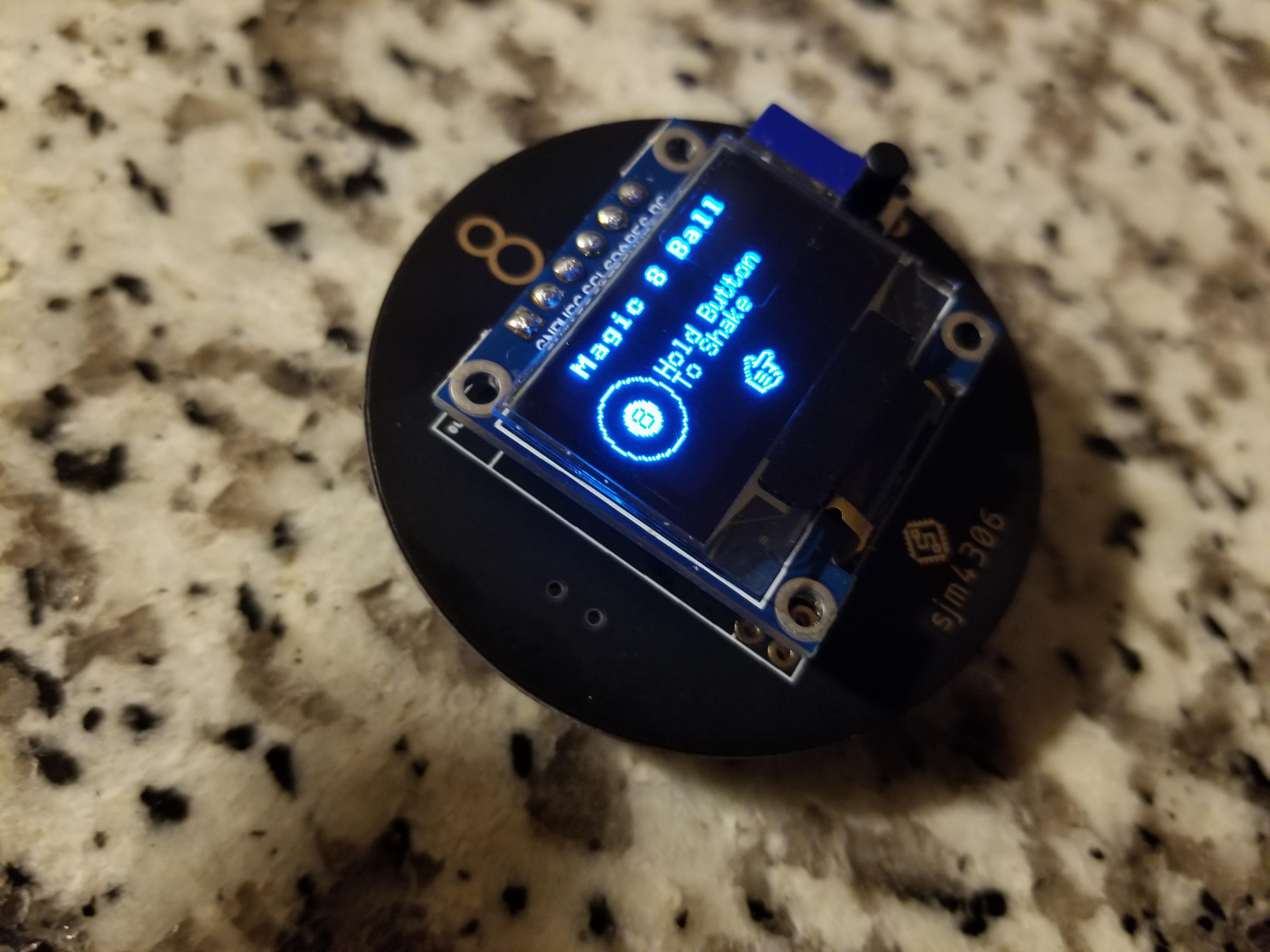
Digital Magic 8 Ball (Mk.2)
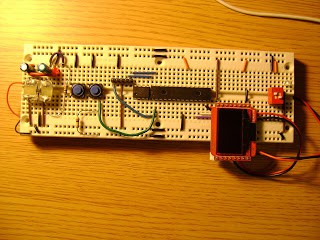
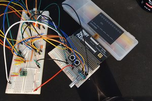
One of my first projects ages ago was a Digital Magic 8 Ball on a breadboard ...
 sjm4306
Become a Hackaday.io member
Already have an account? Log in.
Just one more thing
To make the experience fit your profile, pick a username and tell us what interests you.
Pick an awesome username
hackaday.io/
Your profile's URL: hackaday.io/username. Max 25 alphanumeric characters.
Pick a few interests
Projects that share your interests
People that share your interests
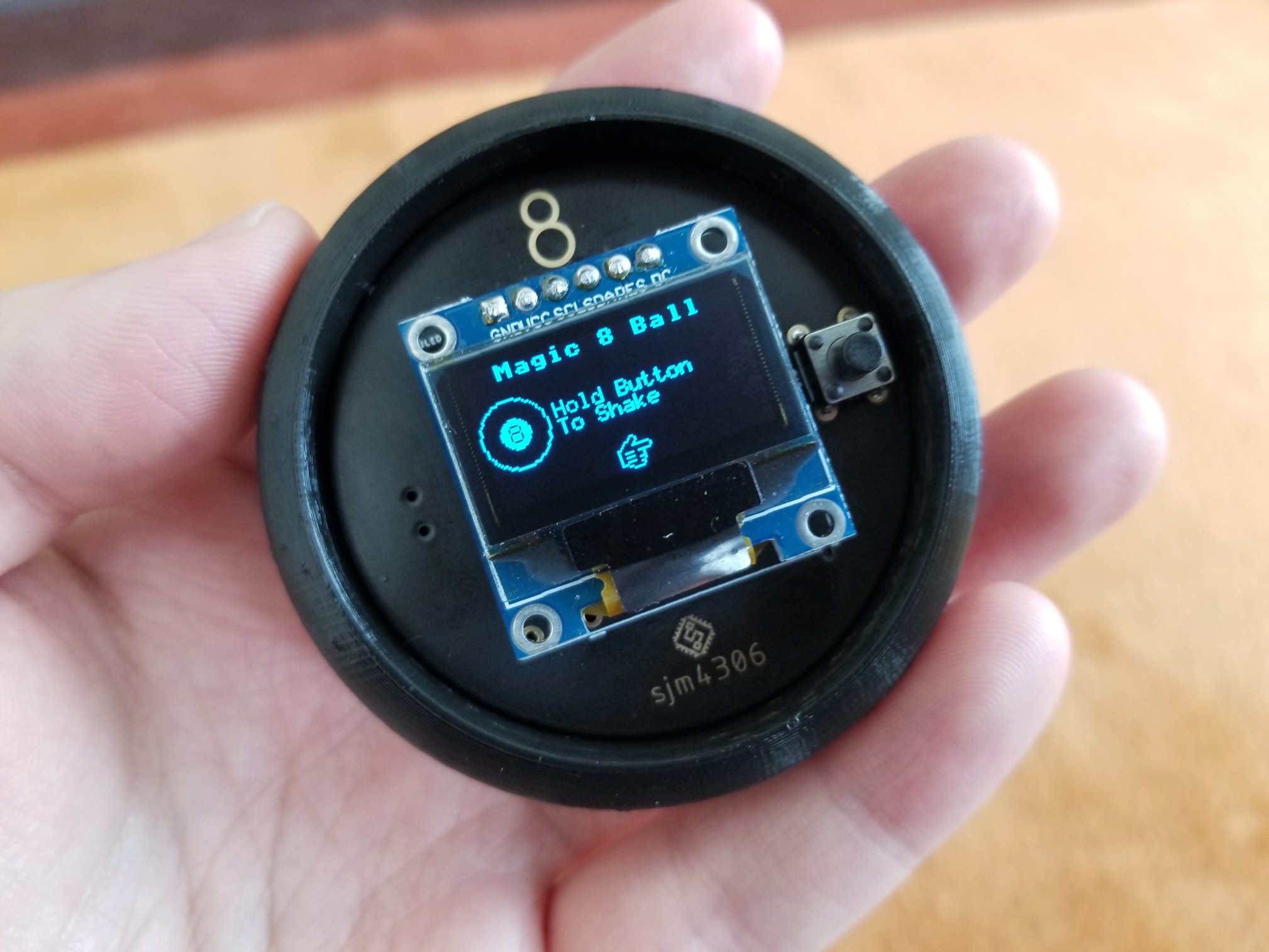
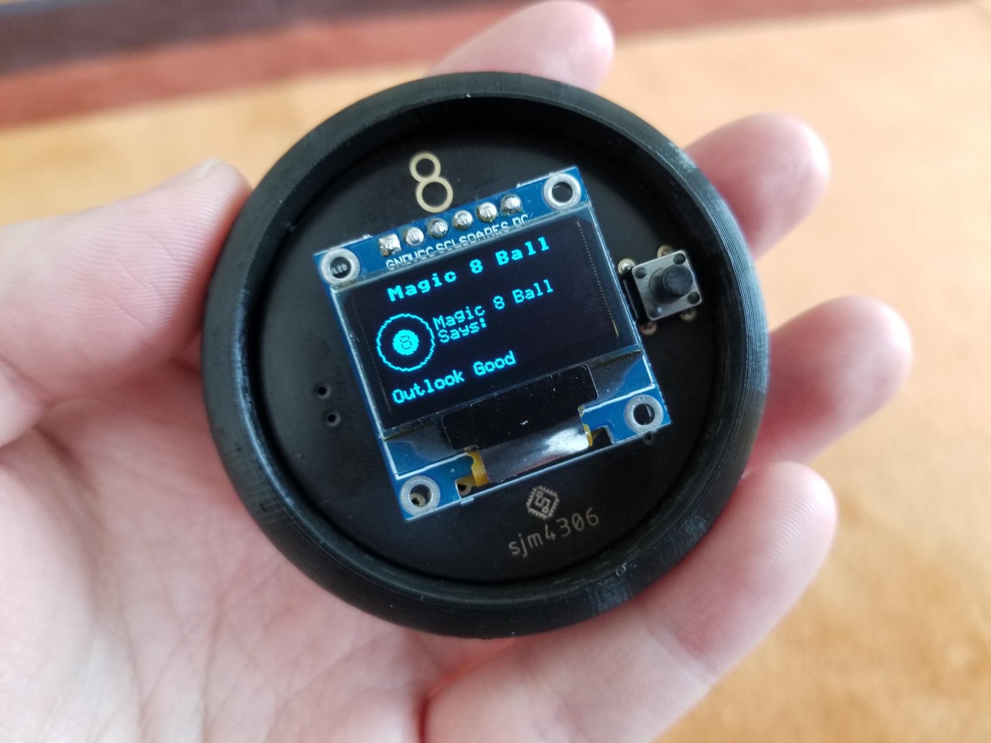
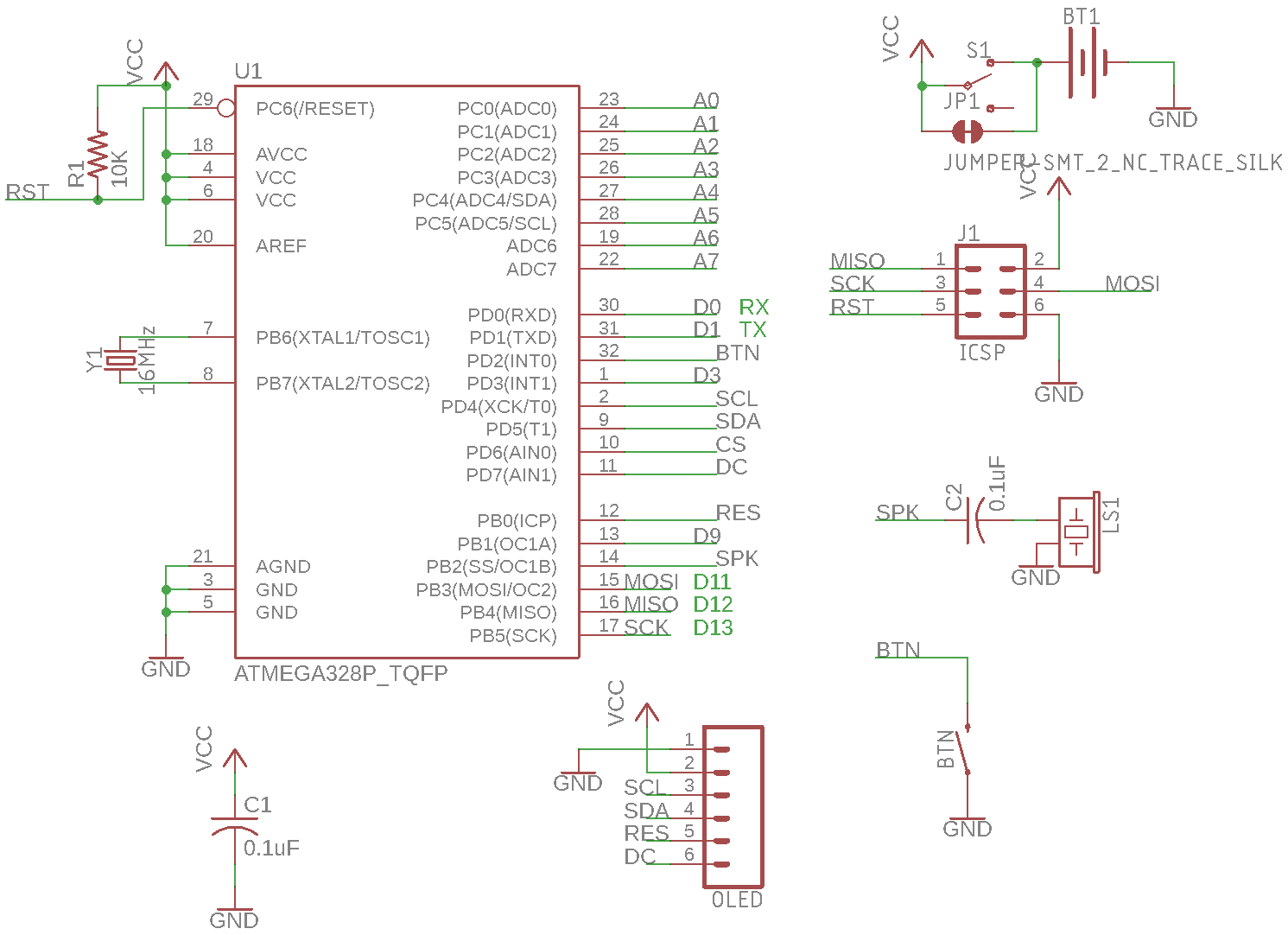
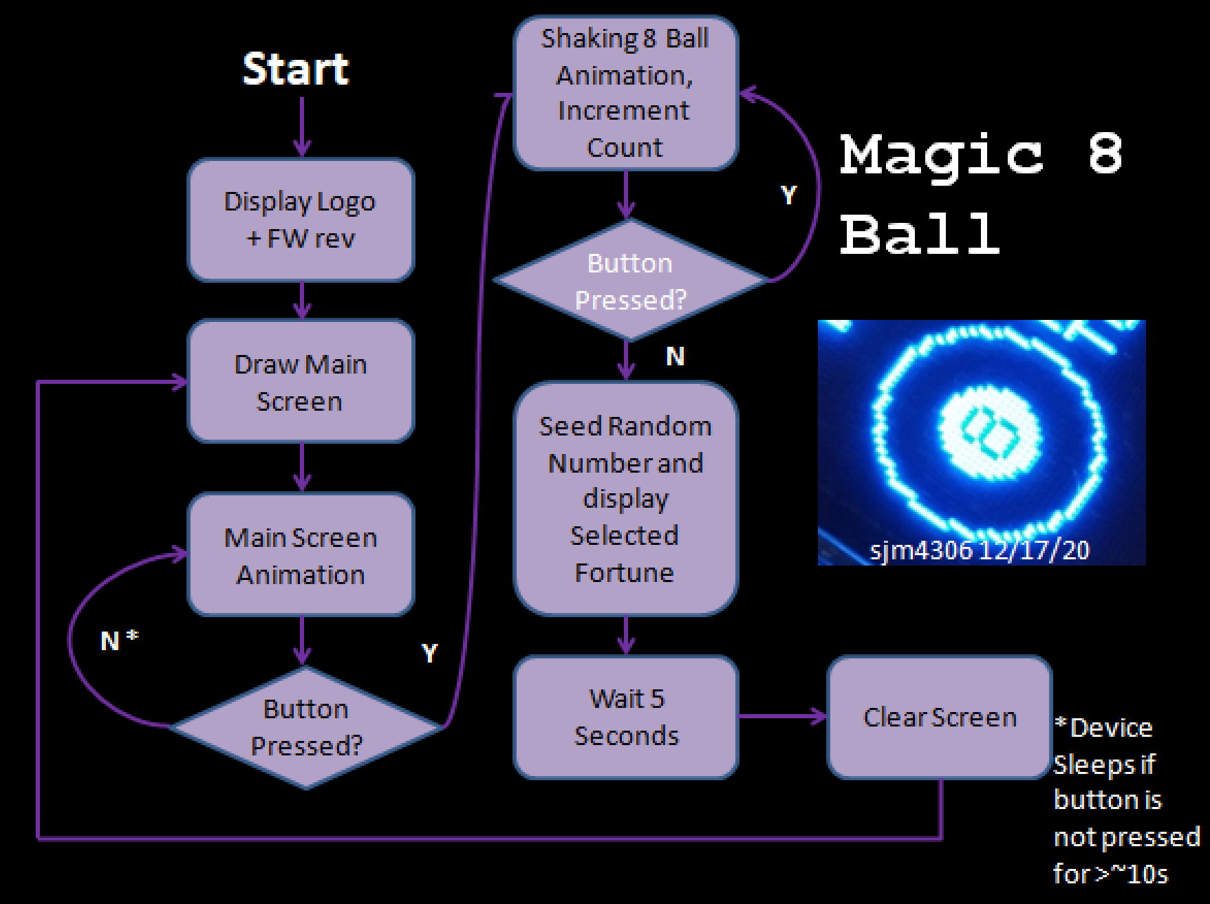 The software is fairly simple with really only three main modes: the main screen, telling a fortune, and sleep. The transition between each mode is initiated as shown in the diagram above.
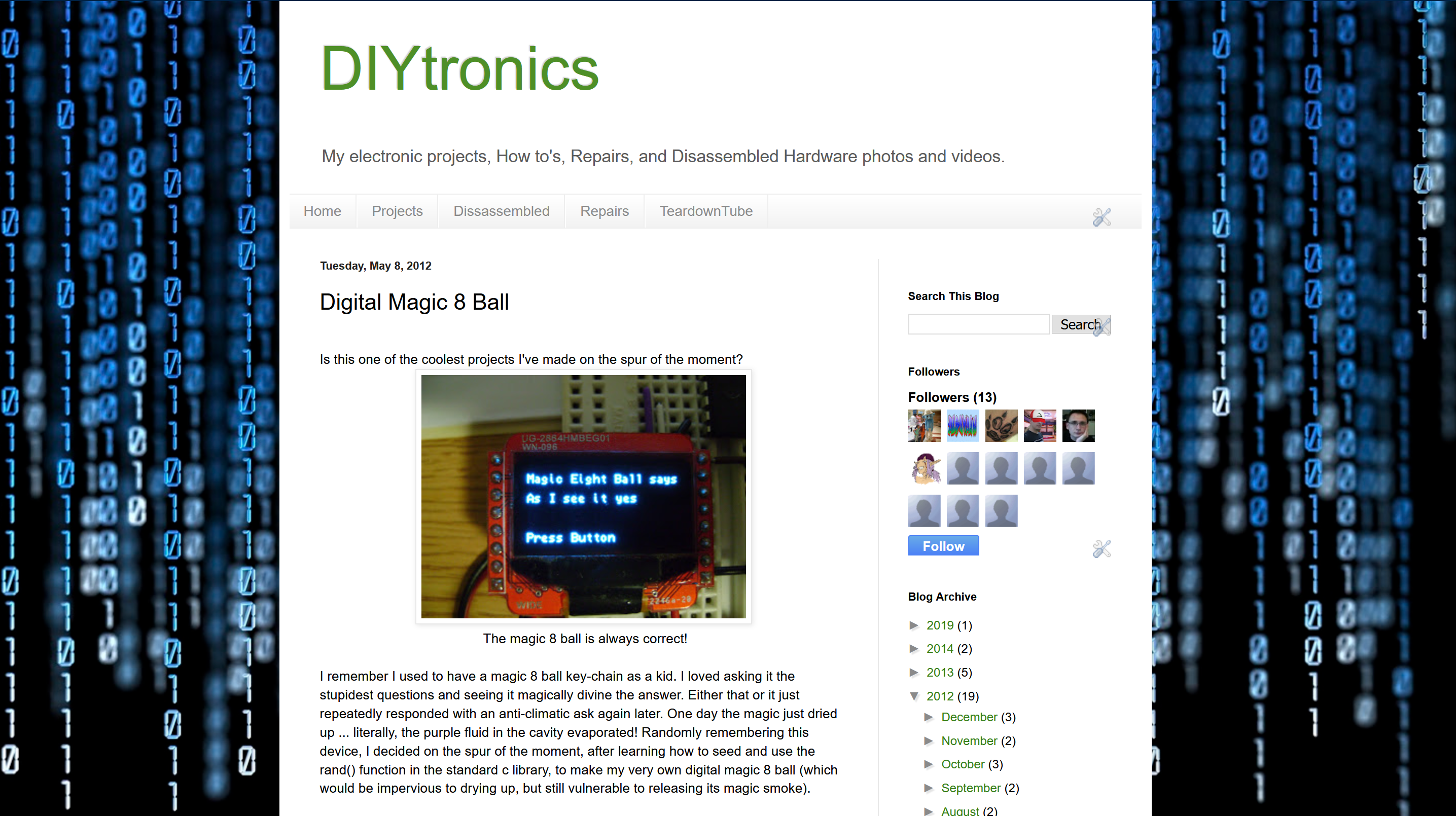
 Jay8ee
 c.Invent
 Miroslav Zuzelka
 mulcmu